Twin boundary-Precise measurement of angular difference
Twin boundary-Precise measurement of angular difference
Convergent-beam electron diffraction (CBED) enables us to determine the angular change at a twin boundary and angular difference at a small-angle grain boundary with a greatly high accuracy of 0.01°, which is two orders of magnitudes higher than the accuracy of 1° obtained by ordinary selected area diffraction (SAD) [1]. The measurement method is described using the twin angle of NiO as an example.
Method to acquire a defocus CBED pattern for measuring the twin angle
Fig. 1 illustrates the method to acquire a defocus CBED pattern to measure the angle of a twinned crystal. Let us consider the case of a twin boundary running oblique to the surface of a specimen. The crystal above the twin boundary (Domain 1) is assumed to have a different orientation from the crystal below the boundary (Domain 2) by an angle δ. By slightly defocusing the cone-shaped incident beam or by shifting the focal point of the beam a little upper from the specimen, the convergent beam is illuminated over an area of both domains across the twin boundary. This is called the defocus CBED method.
The size of the diffraction disks are determined by the size of the condenser aperture. The disk of the transmitted wave and the disk of a diffracted wave are shown. The diffraction lines (principal maxima) of the reflection g from the two domains are shifted, as shown in the figure. The shift corresponds to the change of crystal orientation between the domains above and below the twin boundary. From the ratio between this shift and the distance of the reflection g, the twin angle can be determined with an accuracy as high as 0.01°.
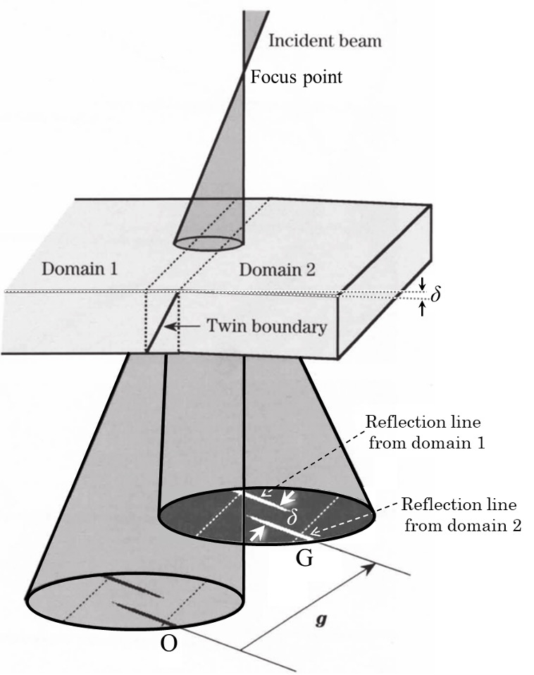
Fig. 1. Schematic of the defocus CBED pattern obtained from the area containing a twin boundary.
A shift is seen between the diffraction lines from Domain 1 and Domain 2 across the twin boundary, in the disks O and G.
The dotted lines in the disks are the projection of the intersecting lines of the twin boundary with the upper and lower surfaces of the specimen.
Shifts of reciprocal lattice points and diffraction lines from a twinned crystal
In order to determine the twin angle with a high accuracy, it is needed to set a specimen so that the shift direction of the reciprocal lattice points from the two domains is almost parallel to the incident electron beam.
Fig. 2 (a) depicts schematically a vector ∆gz representing a shift of the reciprocal lattice points for Domains 1 and 2, together with the direction of the incident electron beam. The Ewald spheres corresponding to incidence A and incidence C are shown by solid lines. The Ewald spheres corresponding to the incident beam directions where the reflection g satisfies the Bragg condition for Domain 1 and 2, are shown by dotted lines.
Fig. 2 (b) illustrates the shift of the diffraction lines appearing in the defocus CBED disks, corresponding to Fig. 2 (a). The distance between the diffraction lines in the transmission disk O and the diffraction disk G (or disk G') corresponds to 2θB, or twice the Bragg angle of the reflection g. The shift of the two diffraction lines in a disk corresponds to the twin angle δ (δ = |∆gz|/|g|).
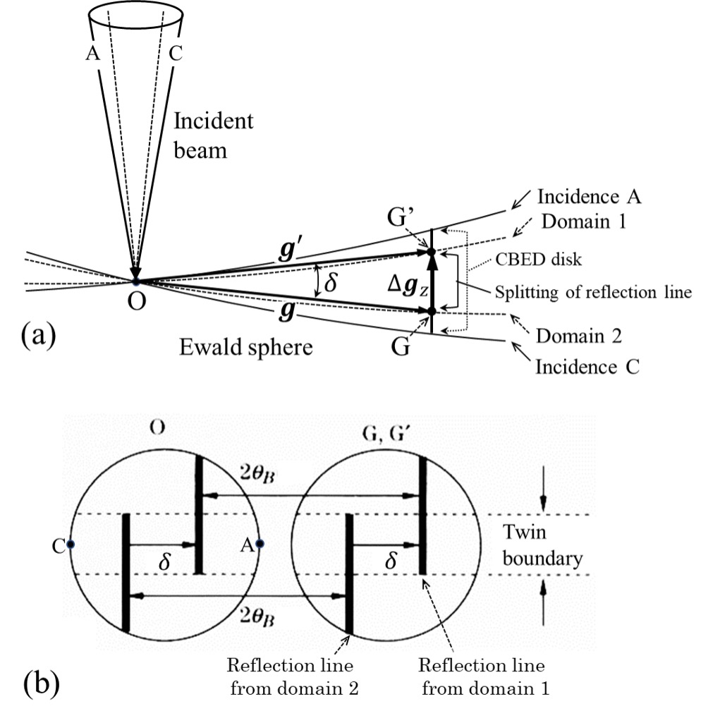
Fig. 2 (a) Schematic of the shift between the reciprocal lattice points G of Domain 1 and G' of Domain 2 of the twins and schematic of the Ewald spheres for the incident beam cone.
The crystal is set so that the vector ∆gz representing the shift of the reciprocal lattice points is almost parallel to the incident beam direction.
(b) Schematic of the shift of the diffraction lines due to the two domains appearing in the defocus CBED patterns.
The distance between the two diffraction lines in the transmission disk O and the diffraction disk G (or disk G') corresponds to 2θB.
The shift of the two diffraction lines in each diffraction disk corresponds to the twin angle δ (δ = |∆gz|/|g|).
Defocus CBED pattern from a twin boundary of NiO (110) and determination of its twin angle
Fig. 3 shows a defocus CBED pattern of a twin boundary of NiO (110) taken at an accelerating voltage of 200 kV. The two diffraction lines in 004, 006 and 008 reflection disks are displaced as illustrated in Fig. 1. The displacement of the lines for each reflection is the same irrespective of the order of reflection. This is because the twin angle is constant independent from the reflection order.
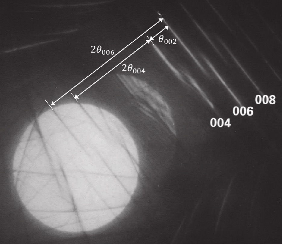
Fig. 3. Defocus CBED pattern obtained from an area containing a twin boundary of NiO (110) taken at an accelerating voltage of 200 kV.
It is seen that the two diffraction lines from the two domains in the 004, 006 and 008 reflections are shifted with the same distance.
The shifts are also seen in the transmission disk at the lower left.
It is noted that in this pattern, the incidence beam angle is set to largely overlap the adjacent diffraction disks.
It should also be noted that the angle between the 004 and 006 diffraction lines does not correspond to 2θ002, but corresponds to θ002.
Fig. 4 shows a bright-field defocus CBED pattern (large-angle convergent-beam electron diffraction pattern) obtained from an area containing a twin boundary of NiO (110) at an accelerating voltage of 200 kV, together with a bright-field TEM image taken from the corresponding area. In the area of the twin boundary indicated by two dotted lines, the shift of the 004 reflection lines is seen (indicated by black arrow pairs).
The distance between the 004 and 006 diffraction lines corresponds to the Bragg angle θ002. Using Bragg's equation 2d sinθB = λ, the angle θ002 was determined to be 0.344° for 200 kV, where d is the distance of (002) lattice pane. The ratio of "the distance of the 004 diffraction lines from the two domains" to "the distance between the 004 and 006 diffraction lines" was measured to be 0.38. Then, the distance of the 004 diffraction lines from the two domains is converted to be an angle of 0.344° × 0.38 ≈ 0.13°. (This angle corresponds to the angle between the (001) planes of Domain 1 and Domain 2.) If this value is converted to the angle of the rhombohedral lattice α, the angle is determined to be α = 90.07°.
NiO belongs to the rhombohedral phase (trigonal crystal system) at room temperature, and the lattice constants are reported to be a = 4.177 Å, α = 90.06° [2]. The value obtained in the above experiment agrees very well with the reported value of 90.06°.
It is noted that the 0k0 reflections exhibit no splitting because the (0k0) planes are common for the both domains and have no angular change.
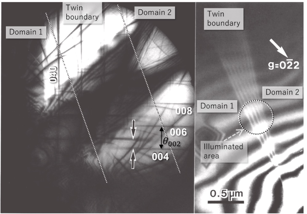
Fig. 4. Bright-field defocus CBED pattern (large-angle convergent-beam electron diffraction pattern) from an area containing a twin boundary of NiO at an accelerating voltage of 200 kV, together with a bright-field TEM image taken from the corresponding area.
The striped area in the TEM image corresponds to the twin boundary. The defocus CBED pattern was acquired from the area enclosed by a dotted circle in the TEM image.
A shift of the 004 reflections from the two domains is seen in the area of the twin boundary as indicated by the black arrows in the CBED pattern.
In summary, when the shift direction of the reciprocal lattice points from the two domains across a twin boundary is set parallel to the direction of the incident beam, the orientation change at the twin boundary can be measured with an accuracy of 0.01°, whereas when the shift direction is set vertical to the incident beam direction, measurement accuracy is only about 1°, as in the case of selected area diffraction.
It should be noted that this method can be applied also to the small-angle grain boundary.
(By Professor Kenji Tsuda, Tohoku University)
References
- [1] M. Tanaka, M. Terauchi and T. Kaneyama, J Electron Microsc. 40, 211-220 (1991).
- [2] R. W. G. Wyckoff, Crystal Structures, Vol. 1, New York, Interscience (1963).
Appendix. The reasons why the defocus CBED method can measure a change in crystal orientation with a high accuracy
Fig. 5 shows the reciprocal lattice points for Domain 1 as black points and those of Domain 2 as gray points. The Ewald spheres for the incident electron beam directions A and C are drawn by straight lines for simplicity, respectively with a dotted line and a solid line. The distance from the reciprocal lattice point to the Ewald sphere is called "excitation error" and this is expressed as s. The angle limited by the Ewald spheres A and C corresponds to the CBED disk size in the lateral direction.
The size or diameter of the diffraction disk g corresponds to the angle 2θ of the convergence angle of the incident beam in the present case. In Fig. 5, since the transmission disk contacts with the diffraction disk g, the convergence angle 2θ of the incident-beam is equal to 2θB. (θB: diffraction angle of the diffracted wave g )
The lines drawn with gray and black colors in the disk show the reflection lines from the Domains 1 and 2 of the twins with a shift of the twin angle δ.
The ratio of this shift to the disk diameter is δ/ (2θ). Since the convergence angle of the incident beam 2θ is approximately 10 mrad (= 0.01 rad) at an accelerating voltage of 200 kV, the shift can be expressed to be δ/ (2θ) = δ×100. This means that the angular difference δ at the twins can be observed to be magnified by a factor of about 100.
This advantage was demonstrated for a high-accuracy measurement of angular difference in the twin domains of NiO, described above.
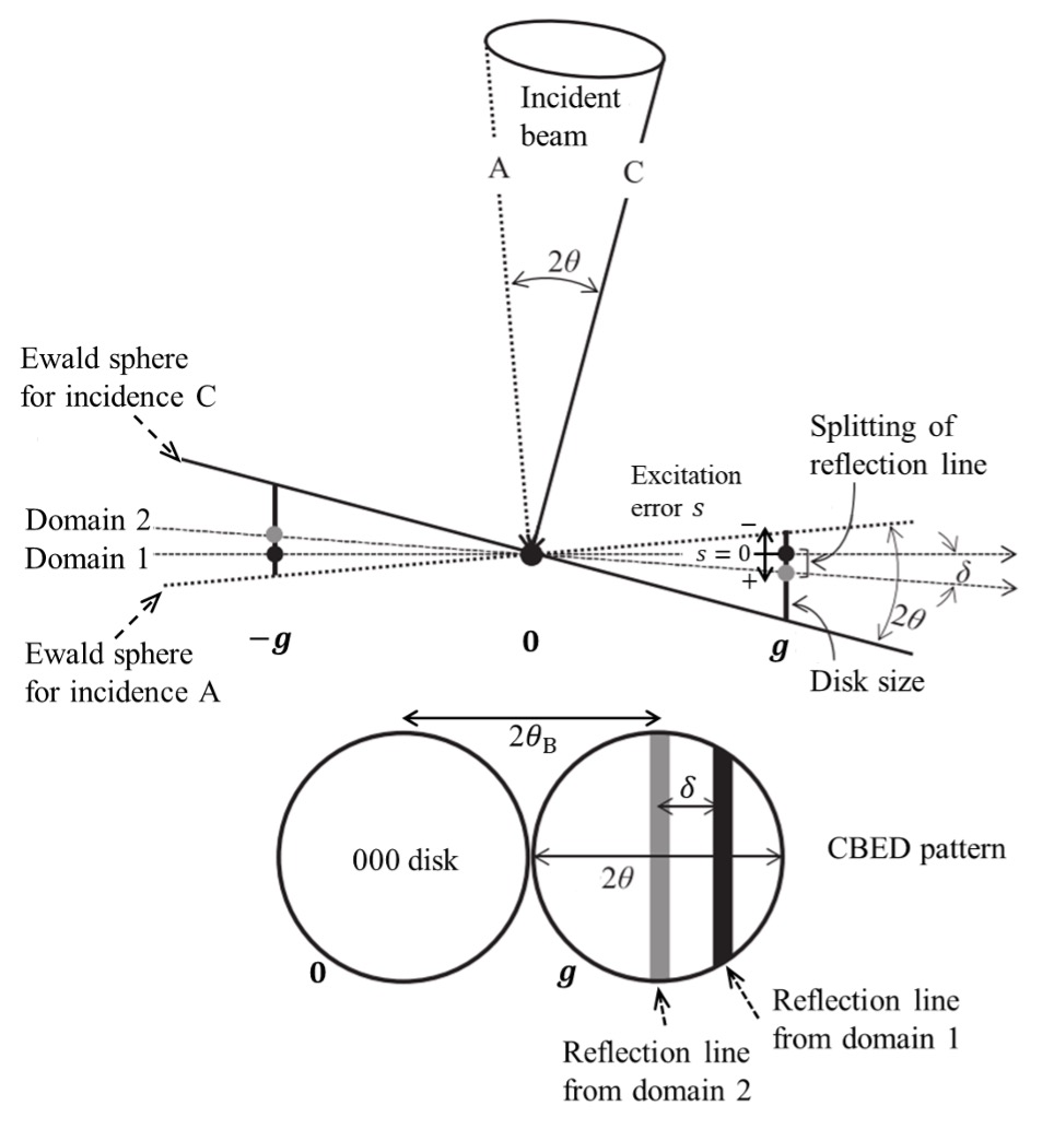
Fig. 5. Relationship between the diffraction line in a CBED disk and the reciprocal lattice point
Related Term(s)
Term(s) with "Twin boundary-Precise measurement of angular difference" in the description

Are you a medical professional or personnel engaged in medical care?
No
Please be reminded that these pages are not intended to provide the general public with information about the products.


