Burgers vector determination of a dislocation using CBED
Burgers vector determination of a dislocation using CBED
The Burgers vector b of a dislocation can be unambiguously determined when convergent-beam electron diffraction (CBED) is applied.
The traditional TEM imaging method uses only the information g ∙ b = 0 to determine the Burgers vector, but the CBED method uses also the information g ∙ b = n ≠ 0 . As a result, the Burgers vector can uniquely be determined without any preliminary information (possible candidates) about the Burgers vector [1, 2].
Fig. 1 illustrates the method to acquire a defocus CBED pattern to determine the Burgers vector. By slightly defocusing the incident convergent beam (shifting the focal point a little upper from a specimen), the convergent beam is illuminated over the whole strained area due to the dislocation. This is called the defocus CBED method. When the principal maximum line of a reflection g intersects with the dislocation line, the reflection line bends or shifts around the intersecting point, as shown in Fig. 1. This is caused by the change of the reflection condition (the diffraction angle) due to the lattice strain by the dislocation.
By computer simulations, it is known that the reflection line exhibits n nodes in the reflection g of a defocus CBED pattern when g ∙ b = n [2]. The sign of n can be determined by the direction of the bend (shift) of the reflection line (described later).
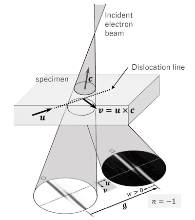
Fig. 1. Schematic of the defocus CBED method, which takes diffraction patterns from the whole strained area due to a dislocation.
Here, g is the reflection vector, u is the vector of the dislocation line, c is the vector which points from the center of the illuminated specimen area to the focus position of the incident beam, the vector v is defined by the equation v = u × c, and w is the dimension-less quantity w = sξg , where s is the excitation error and ξg is the extinction distance.The direction of w > 0 is from the reflection g to the transmitted wave.
Next, count the number of nodes n for three reflections g, where these three reflections have to be linearly independent, that is, they are not in the same plane (same Laue zone). Let the Burgers vector be b = [uvw], and b is unambiguously obtained by solving the ternary linear equation g ∙ b = n.
The sign of is determined by the following way. The direction of the Burgers vector is defined by the FS/RH convention [3]. Since the direction of the dislocation line is arbitrary, the direction is taken in the direction of the arrow u as shown in Fig. 1(a). Let c be the vector from the center of the illuminated area on the specimen to the focus of the incident beam. Here, the vector v is defined as v = u × c. The origin of v is taken on the dislocation line, and we look the side v > 0 across the dislocation line. n is negative if the bend of the diffraction line (the direction of deviation from the straight line) on the side v > 0 is the same as the direction of the reflection vector g (as seen in Fig. 1).
n is positive if the bend is in the opposite direction of g. In Fig. 1, a case of n = −1 is shown.
Fig. 2 shows a defocus CBED pattern taken by illuminating an electron beam to cover the strained area caused by the dislocation of Si.
Let the Burgers vector of the dislocation be b = [uvw], and we make the ternary linear equation g ∙ b = n for three reflections g , for example, 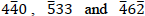 reflections. Then, we obtain the following equations,
−5u + 3v + 3w = −4
−4u + 6v − 2w = −1.
By solving these equations, b = ![reflection [101]/2](/words/emterms/glossary_file/file/burgers_vector_03.png) is unambiguously obtained.
is unambiguously obtained.
For the other reflection  , if we calculate g ∙ b using the obtained b, we find that g ∙ b = 6, which is consistent with the value of n read from the CBED pattern, n = +6.
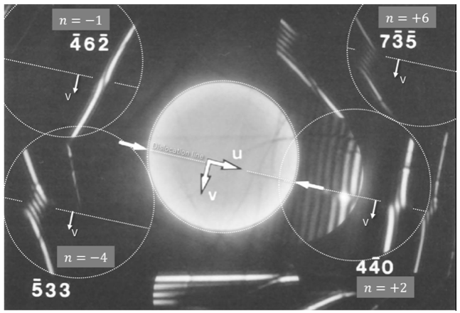
Fig. 2. Defocus CBED pattern taken from the dislocation of Si.
Each diffraction disk is indicated by a white dotted circle, and the dislocation line appearing in each reflection is indicated by a white dot line. Each value of n, determined by the number of nodes and the bending (shift) direction of the reflection line is written.
For  and
and  reflections, the bending direction of the diffraction (reflection) line at the side of v > 0 is opposite to the direction of the vector g, then the sign of n is positive. On the other hand, for
  and
and  reflections, the bending direction of the diffraction line at the side of v > 0 is the same as the direction of the vector g, then the sign of n is negative.
(By Professor Kenji Tsuda, Tohoku University)
References
[1] D. Cherns, A.R. Preston, Proc. of the 11th Int. Congr. on Electron Microsc., Japanese Society of Electron Microsc., Kyoto, 1986, p. 721-722.
[2] M. Tanaka, M. Terauchi and T. Kaneyama, J Electron Microsc. 40, 211-220 (1991).
[3] J.P. Hirth and J. Lothe, Theory of dislocations (2nd ed.), Wiley, New York (1982).
Related Term(s)
Term(s) with "Burgers vector determination of a dislocation using CBED" in the description

Are you a medical professional or personnel engaged in medical care?
No
Please be reminded that these pages are not intended to provide the general public with information about the products.


