Vortex electron wave
Vortex electron wave
A vortex electron wave is an electron wave that propagates in a space with a spiral wavefront (or a spiral equiphase plane). Since the wavefront of the electron wave is of a spiral shape, only waves which create an advance of ℓ(ℓ= integer) times the wavelength in the axial direction is allowed for one turn about the central axis along the equiphase plane. Here, ℓ is called topological number, topological quantum number or topological charge, and is a parameter characterizing the vortex wave. Since the physical quantity characterizing a rotation is the angular momentum, a phase rotation with respect to the central axis can be considered to have an (orbital) angular momentum. This means that the vortex electron wave is a wave carrying an orbital angular momentum. The orbital angular momentum is given by ℓ×h/2π, where h is the Planck constant.
In 2010, Uchida and Tonomura experimentally demonstrated the formation of a vortex electron wave using a spiral-shaped phase plate. In their experiment, a plane electron wave was incident onto a graphite with a spiral-shaped thickness change. The transmitted electron wave was interfered with a reference wave which does not pass through the graphite. Then, they confirmed that the transmitted wave has a spiral-shaped wave front or is a vortex wave. Afterwards it was found that the vortex electron wave can be formed also using a fork-shaped grating (Fig.1a), a spiral zone plate (Fig.1b), etc.
A vortex light wave was discovered in 1992. It has been used for rotation operation of light tweezers by transferring the orbital angular momentum of the wave. For the vortex electron wave, magnetic imaging is expected by utilizing interactions between magnetic material and magnetic moment of the vortex electron wave originating from the spiral rotation of electrons.
The upper figures of Fig.2 show the equi-phase planes of vortex electron waves. The wave with ℓ= 0 expresses a plane wave. A point on the orange plane comes back to the same point for one turn about the central axis. The vortex wave of ℓ= 1 creates an advance of one-wave length in the axial direction for one turn on the equi-phase plane about the central axis, which is illustrated by orange planes. The vortex wave of ℓ= -1 creates an advance of one-wave length in the opposite direction for one turn on the equi-phase plane about the central axis. The vortex wave of ℓ= 2 creates an advance of two-wave length in the axial direction for one turn on the equi-phase plane. Green planes in Fig.2 are drawn for easily recognizing the two-wave length progress of the orange planes. The vortex wave of ℓ= 3 creates an advance of three-wave length for one turn on the equi-phase plane. Purple and green planes are drawn for easily finding the three-wave length progress of the orange planes.
The lower figures of Fig.2 show the intensity distribution of the vortex electron wave for the vertical cross section of the wave. Since the vortex electron wave does not have a fixed phase at the central axis (a phase singular point), the vortex wave is unable to have a finite amplitude on the central axis. As a result, the intensity on the central axis must be zero (dark spot) for the vortex waves (ℓ≠ 0). For ℓ= 0 (plane wave) the wave does not have any angular momentum and any singular point, and the intensity on the central axis takes a maximum value. The larger ℓ is, the larger the radius of the intensity ring becomes.
In Fig.3, a diffraction pattern taken by illuminating a parallel electron beam onto a fork-shaped grating is shown. The intensities of the diffracted waves at the both sides of the transmitted wave are ring-shaped and have dark spots at the respective centers (see the lower figures of Fig.2). This result confirms that the detected electron wave is a vortex electron wave.
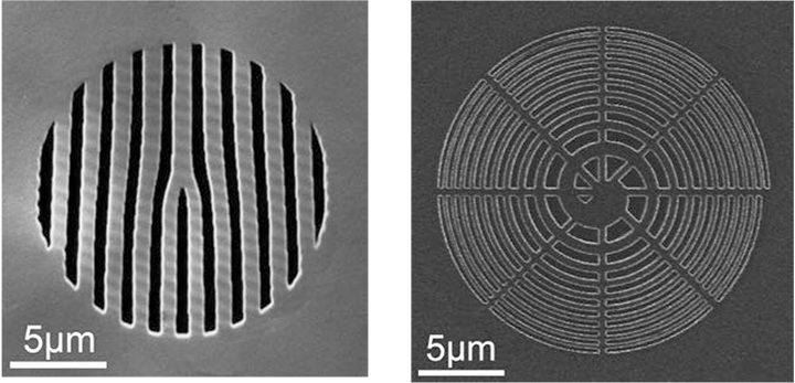
Fig.1 Platinum mask to form a vortex electron wave by passing a plane electron wave through it.
(a) Fork-shaped grating mask and (b) Spiral zone plate mask.
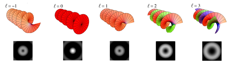
Fig. 2 Schematics of equi-phase plane of the vortex wave (top) and radial intensity distribution of the wave (bottom).
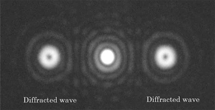
Fig. 3 Examination of the vortex electron wave.
Diffraction pattern taken by passing a parallel electron beam through a fork-shaped grating mask. The diffracted waves at the both sides of the transmitted wave have ring-shaped intensity distributions and dark spots at the respective centers. This confirms that the detected electron wave is a vortex electron wave.
Term(s) with "Vortex electron wave" in the description

Are you a medical professional or personnel engaged in medical care?
No
Please be reminded that these pages are not intended to provide the general public with information about the products.


