electron holography
electron holography
"Electron holography" is a technique to reconstruct phase changes suffered by a specimen by utilizing the coherency of electron waves.
The scattered wave transmitted through the specimen (object wave: suffering a phase change) and the wave traveling from the electron source and passing through vacuum (reference wave: not influenced by the specimen) are deflected by an electron bi-prism and superposed each other, and then interference fringes or an electron hologram is formed. By applying Fourier transform to the obtained hologram using a computer, a spectrum of the hologram is obtained. Then, the equally spaced, main interference components forming the background in the present case are removed by masking, and modulation components due to the specimen or the diffracted waves (the side-band spectra) are extracted. The modulation components are subjected to inverse-Fourier transform. As a result, the phase changes at the bottom plane of the specimen are reconstructed.
A field-emission electron gun with a small electron source is required because a highly coherent beam is crucial to obtain the hologram. This technique was proposed by Gabor (awarded Nobel Prize in Physics in 1971) to remove aberrations in a TEM. However, nowadays the electron holography technique is widely used for observation of electric and magnetic fields in a very small (micro- to nano-meter scale) specimen area.
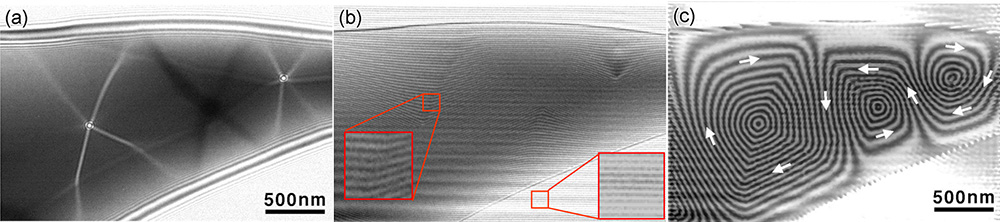
(a) Lorentz TEM image, (b) Electron hologram and (c) Phase reconstruction image of a rapidly frozen magnetic material Fe73.5Cu1Nb3Si13.5B9.
In the Lorentz TEM image (a), the boundaries of a magnetic domain (magnetic domain walls) appear as bright or dark lines. Increasing the defocus broadens the width of the bright and dark lines. When the sign of defocus is reversed, bright lines and black lines are interchanged. In the electron hologram (b), interference fringes are observed, which are obtained by deflecting the wave transmitted through the specimen (object wave) and the wave transmitted in vacuum (reference wave) using an electron bi-prism so as to be superposed each other.
The large square at the left shows an enlarged image of the small square area. Interference fringes between the object wave and the reference wave are seen, where the bend and spacing change of the fringes are found. A large square at the bottom right shows the enlarged image of the small square area, where the interference fringes at the vacuum region are seen. Since there is no phase change due to the specimen, these interference fringes are equally spaced and straight.
Bright or dark lines in the phase reconstruction image (c) show equi-phase lines. The directions of the lines indicate the directions of magnetic flux (shown by white arrows) and fringe spacings show the magnitudes of the magnetic flux. A region where the equi-phase lines are almost straight and arranged in the same direction exhibits one magnetic domain. Magnetic domain walls exist at the sudden bends (~90 degrees) of the equi-phase lines. It is found that the sudden bends of equi-phase lines in the electron hologram (c) correspond to the bright or dark lines in the Lorentz TEM image (a).
(Courtesy of the images: Professor D. Shindo, Tohoku University)
Related Term(s)
Term(s) with "electron holography" in the description

Are you a medical professional or personnel engaged in medical care?
No
Please be reminded that these pages are not intended to provide the general public with information about the products.


