δ fringe
δ fringe
"δ fringe" means the edge fringes showing a specific contrast of the striped interference image obtained from a twin boundary oblique to a crystalline specimen surface, which appears in bright- and dark-field images taken at a two-wave approximation condition. (The twin boundary is formed by two crystalline parts with different orientations.)
Fig.1(a) shows a schematic of a twin boundary oblique to the specimen surface and the expected striped interference image or the δ fringe from the boundary. The lattice planes change their orientations at the twin boundary. Fig. 1(b) shows the dark-field image of a twin boundary of nickel oxide (NiO). Fig. 1(c) shows an enlarged image of a part of Fig. 1(b).
The excitation error s of diffracted wave g is different for the two crystalline regions of the twin. The sign of the difference Δs = s1 - s2 between the excitation errors s1 and s2 for the two regions, determines the nature of the end-striped image or the contrast of the δ fringe. The nature and formation of the striped image is explained by the dynamical diffraction theory taking account of the absorption effect. (see Reference: Marc De Graef: Introduction to Conventional Transmission Electron Microscopy, pp507~).
The end stripes or δ fringes, which appear at the intersection between the twin boundary and the upper and lower surfaces of the specimen, exhibit symmetric contrast in the dark-field image and anti-symmetric contrast in the bright-field image with respect to the center of the striped image (to the half depth position of the specimen). The symmetric contrast (nature) in the dark-field image or a bright (B)- and bright (B)-fringe pair is clearly seen in Fig. 1(b) and (c).
This symmetry nature reveals the sign of Δs (Δs is positive in Fig. 1(b)), and the sign of the angle between the two crystalline regions (the right region is upward to the left region or downward to the left). The term "δ fringe" is originated from the angular change "δ" between the crystalline regions at the twin boundary.
The symmetry nature above described appears only when the angular difference between the two crystalline regions is several degrees or less. If the angle becomes large, only one crystalline region satisfies the Bragg condition, that is, the excitation error s for the other region becomes large, the symmetry nature of the end stripes or the δ fringe disappears, and instead, equal thickness fringes appear from the former region where the diffraction condition is satisfied. Thus, understanding of the δ fringe together with the α fringe is one of the great successes of the dynamical diffraction theory taking account of the absorption effect. However, the angle between the two crystalline regions is difficult to be measured using the δ fringe.
It should be noted that the measurement of the angular difference between the two crystalline regions can be performed by the large-angle convergent-beam electron diffraction (LACBED) with a very high accuracy. The following references are referred to detailed LACBED analysis.
- M. Tanaka, M. Terauchi and T. Kaneyama: J. Electron Microscopy 40 (1991) 211-220
- M. Tanaka, M. Terauchi and K. Tsuda: Convergent Beam Electron Diffraction III (1994) pp188-205, JEOL Tokyo
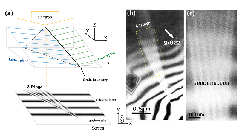
Fig. 1(a) Schematic of a twin boundary oblique to a wedge-shaped specimen (top) and the illustration of the δ fringe (bottom).
Fig. 1(b) Dark-field image of a twin boundary oblique to the specimen surface, showing striped images and δ fringes. A bright (B)- and bright (B)-fringe pair is seen at the ends of the stripes (symmetric with respect to the center of the stripes). Specimen: NiO. Accelerating voltage: 200 kV.
Fig. 1(c) Enlarged image of (b) indicated by a yellow dotted line. The bright (B)- and bright (B)-fringe pair is more clearly seen at the both ends of the stripes.
Related Term(s)
Term(s) with "δ fringe" in the description

Are you a medical professional or personnel engaged in medical care?
No
Please be reminded that these pages are not intended to provide the general public with information about the products.


