scanning transmission electron microscope image, STEM image
scanning transmission electron microscope image, STEM image
"Scanning transmission electron microscope (STEM) image" is obtained as follows. A small-sized, focused electron probe is scanned over a thin specimen using the double-deflection system. The intensity of the transmitted wave (or the diffracted wave) exiting from a point on the specimen is detected with an annular detector. Then, the intensities are displayed on a computer monitor as a series of bright spots in synchronism with the scanning electron-probe. The resolution of the STEM image is determined by the probe diameter. The STEM method has two observation modes; bright-field mode and dark-field mode.
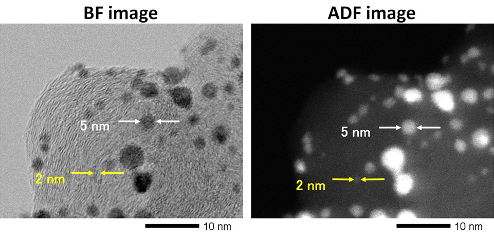
Fig. Bright-field (left) and annular dark-field (right) STEM images of Pt catalyst particles on a graphite support.
In a bright-field (BF) image, Pt particles appear dark because the incident electrons are scattered at high-angles. In an annular dark-field (AF) image, Pt particles appear bright or show reversed contrast to the BF image because the scattered electrons at high angles are received by the ADF detector.
Related Term(s)
Term(s) with "scanning transmission electron microscope image, STEM image" in the description

Are you a medical professional or personnel engaged in medical care?
No
Please be reminded that these pages are not intended to provide the general public with information about the products.


