extinction rule
extinction rule
The extinction rule means in what case forbidden reflections occur. (Forbidden reflections mean the extinction of reflections due to the crystal structure factor being 0 (zero) even when the Bragg condition is satisfied.) The extinction of the reflections occurs due to the type of the crystal lattice and due to the symmetry element of the space group. In the former case, reflections vanish in both the kinematical diffraction case and the dynamical diffraction case (Fig. 1). In the latter case, i.e. due to glide planes or screw axes (symmetry elements of the space group), the extinction of the reflections occurs only when kinematical diffraction applies. When the dynamical diffraction effect occurs, the forbidden reflections can have certain intensity (Fig. 2). However, when there exists "Umweganregung", an extinction occurs at a part of the reflections under specific beam incidence conditions. The extinction appears as a dark line in kinematically forbidden reflections in a CBED pattern (Figs. 3 and 4).
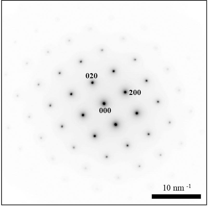
Fig. 1. Extinction of reflections due to the type of the crystal lattice.
Electron diffraction pattern of Cu taken at the [001] electron incidence, where Cu takes the face-centered cubic lattice. In the case of the face-centered cubic lattice, for the reflections h, k, l having even- and odd-numbered mixed indices, the crystal structure factor takes zero or F (h k l) = 0. Thus, the diffraction spots vanish. In this figure, it is seen that the diffraction spots of 100 and 110, etc., vanish. The pattern was taken with the JEM-2100Plus at an accelerating voltage of 200 kV.
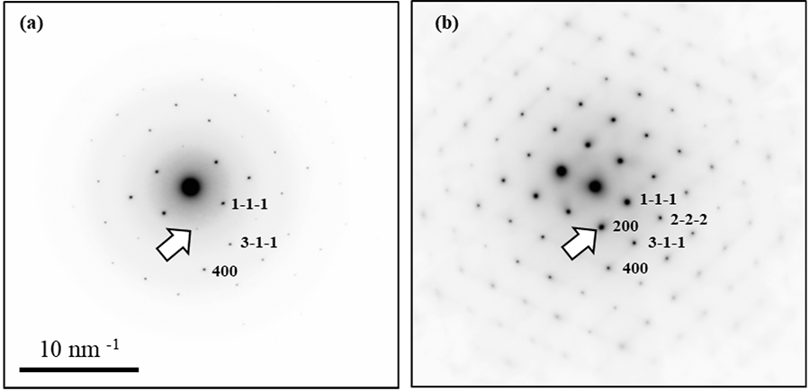
Fig. 2. Extinction of reflections due to a symmetry (d-glide plane) element of the space group.
Electron diffraction patterns of Si taken at the [01-1] electron incidence, Si crystal having d-glide planes. (a) a sufficiently thin specimen and (b) a thick specimen. Extinction of the reflections due to the d-glide planes occurs when reflection indices take h+k+l = 4n+2 (n is integer). The 200 reflection (indicated by an arrow in Fig. 2(a) and (b)) is forbidden kinematically but has a certain intensity due to "Umweganregung" or successive excitation of the 1-1-1 reflection and the 111 reflection as an example. In the case of a thin specimen (a), "Umweganregung" is weak and thus, the 200 reflection is weak. In the case of the thick specimen (b), "Umweganregung" is strong and thus, the reflection is strong. The patterns were taken with the JEM-F200 at an accelerating voltage of 200 kV.
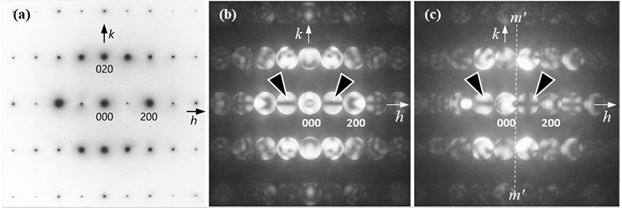
Fig. 3. Partial extinction (dark lines) in the reflections excited by "Umweganregung". (Data courtesy: Professor Kenji Tsuda, Tohoku University)
Diffraction patterns of FeS2. (a) a selected-area diffraction pattern taken at the [100] electron incidence, (b) a convergent-beam electron diffraction (CBED) pattern taken at the [100] electron incidence and (c) a CBED pattern taken at the electron incident slightly tilted from the [001] zone axis to excite the 100 reflection.
FeS2 belongs to the space group of P21/a3 and has a-glide plane in the (010) plane and 21 screw axis parallel to the a-axis. Owing to these symmetry elements, the odd-order h00 reflections have certain intensities due to the dynamical effect ("Umweganregung"). However in those reflections, dark lines are created due to dynamical extinction (shown by arrowheads in Fig.(b) and (c)). The "dynamical extinction" should be referred to the description in Fig. 4. The patterns were taken with the JEM-2010 at an accelerating voltage of 100 kV.
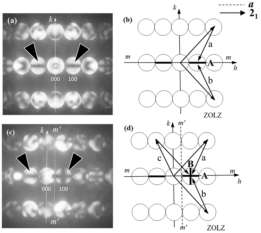
Fig. 4. "Umweganregung" via the zeroth-order Laue zone reflections (ZOLZ reflections) and dynamical extinction (dark lines) appearing in the CBED patterns. (a), (c) Enlarged figures of Fig. 3 (b), (c). (b), (d) Schematic illustrations of dynamical extinction.
We assume that a-glide planes exist in the (010) planes and 21 screw axes exist parallel to the a-axis. Then, the odd-order h00 reflections vanish kinematically. However, these reflections have certain intensities due to the dynamical diffraction effect ("Umweganregung"). It should be noted that dynamical extinction (dark lines) is produced in the CBED disks excited by "Umweganregung" (dark lines in the odd-order reflections).
In Fig. (a), the dark line A is seen horizontally in the odd-order h00 reflections. The "Umweganregung" paths a and b, shown in Fig. (b), are symmetric to both the glide plane and the screw axis. Taking account of the phases of the reflections in each path, the resultant reflections passing through the paths a and b cancel out each other, forming the dark line A. The dark line A appears in all the odd-order reflections.
Fig. (c) shows the case where the odd-order 100 reflection satisfies the Bragg condition, exhibiting the single dark line B perpendicular to the dark line A in the 100 reflection. Fig. (d) shows the "Umweganregung" paths a and c. Both the paths are symmetric to the dotted line m’-m’, and the reflections passing through these two paths cancel out each other, forming the dark line B. For more details, refer to the following references.
(Proofread by Professor Kenji Tsuda, Tohoku University)
References:
M. Tanaka, M. Terauchi, K, Tsuda, "Introduction to Electron Diffraction and Elementary Crystallography (in Japanese)", (Kyoritsu Printing Co., Ltd.) p121
M. Tanaka, "International Tables for Crystallography", Vol. B, 2nd online ed., §2.5.3, (International Union of Crystallography, Chester, 2010)
M. Tanaka and M. Terauchi, "Convergent Beam Electron Diffraction" (JEOL-Maruzen, Tokyo,1985) p50 (http://www2.tagen.tohoku.ac.jp/lab/terauchi/html/activity/cbedbook.html )
Related Term(s)
Term(s) with "extinction rule" in the description

Are you a medical professional or personnel engaged in medical care?
No
Please be reminded that these pages are not intended to provide the general public with information about the products.


