Scherzer focus
Scherzer focus
Scherzer focus is the focus condition of the objective lens for forming the crystal structure image of a thin specimen in the TEM mode (also called "Scherzer defocus"). The focal length (defocus amount) of the objective lens is adjusted depending on the spherical aberration of the objective lens so that the phases of the diffracted waves relative to the transmitted wave are shifted by a quarter wavelength (or a phase shift of π/2) over as wide a spatial frequency range as possible.
For a thin specimen for which the weak phase object approximation can be applied, the diffracted waves are out of phase against the transmitted wave by π/2. That is, the transmitted wave takes a real number, each diffracted wave does an imaginary number. As a result, the superposition of the diffracted waves and the transmitted wave does not produce an image of the specimen because the amplitudes of those waves do not add up.
However, by adjusting the focal length (defocus amount) of the objective lens depending on the spherical aberration of the objective lens, the phase of the diffracted wave can be shifted by a further π/2 (π in total). Then, the diffracted waves become real like the transmitted wave. When these diffracted waves are interfered (superposed) with the transmitted wave, the amplitudes of all the waves are added and the image of the specimen is produced.
The amount of defocus or the Scherzer focus dfSch is given by the following equation using the spherical aberration coefficient CS and the electron wavelength λ [1].
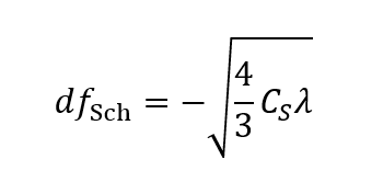
The equation indicates that dfSch takes a negative value. This means that, at an underfocus (excitation of the objective lens is weaker than the in-focus), the structure image is obtained. The absolute value of the defocus amount is larger as CS is larger and as the wavelength of the incident electron is larger (as the accelerating voltage is lower).
When the amount of defocus is set to dfSch, the distance corresponding to the spatial frequency at which the value of the phase-contrast transfer function firstly reaches zero, is given by the equation.
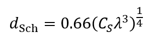
dSch is called the spatial resolution of the image of a weak phase object (Scherzer resolution). The Scherzer resolution is proportional to both the 1/4 cube of the spherical aberration coefficient CS and the 3/4 cube of the wavelength λ. Thus, for attaining a high spatial resolution, the objective lens with a small CS is required and a shorter wavelength (higher accelerating voltage) is favored.
| Accelerating voltage [kV] |
Spherical aberration coefficient [mm] |
Scherzer focus [nm] |
Scherzer resolution [nm] |
|---|---|---|---|
| 100 | 0.5 | -50 | 0.26 |
| 1.0 | -70 | 0.31 | |
| 200 | 0.5 | -41 | 0.20 |
| 1.0 | -58 | 0.23 | |
| 300 | 0.5 | -36 | 0.16 |
| 1.0 | -51 | 0.20 | |
| 1000 | 1.0 | -34 | 0.11 |
Table. Examples of the Scherzer focus (defocus amount) and the Scherzer resolution for typical accelerating voltages and for the spherical aberration coefficients CS of 0.5 mm and 1.0 mm.
In the case of a TEM with an ordinary accelerating voltage of 300 kV, the Scherzer resolution is 0.16 nm for CS = 0.5 mm. In the case of a TEM with a high accelerating voltage of 1000 kV, the Scherzer resolution is as high as 0.11 nm even for CS = 1.0 mm.
Reference
[1] David B. Williams and C. Barry Carter, "Transmission Electron Microscopy: A Textbox for Materials Science", Springer.
[Note]
In a TEM equipped with a spherical aberration corrector (Cs corrector), the spherical aberration coefficient Cs can be set to 0 (zero). In such a case, the equations of the Scherzer focus and the Scherzer resolution cannot be used, because these equations are derived with assuming CS ≠0. If CS = 0 is substituted into the Scherzer focus equation, the defocus amount dfSch becomes zero. Although the image of the weak phase object should not be observable at the in-focus, this concludes that the crystal structure image can be observed at the in-focus.
In reality, in the case of a TEM equipped with a Cs corrector, the crystal structure image can be observed by setting the appropriate defocus, as in the case of a TEM without Cs corrector. Moreover, the frequency of the first zero can be considerably higher than without the Cs corrector, or a higher resolution can be attained. It is noted that the resolution of a TEM equipped with a Cs corrector is not determined often by the frequency of the first zero, but by the energy spread of the electron beam and the stability of the microscope instrument (by an envelope function).
For example, in a TEM equipped with a field-emission gun (FEG) and a Cs corrector, a resolution better than 0.1 nm is obtained at an accelerating voltage of even less than 300 kV.
Related Term(s)
Term(s) with "Scherzer focus" in the description

Are you a medical professional or personnel engaged in medical care?
No
Please be reminded that these pages are not intended to provide the general public with information about the products.


