condenser-objective lens (C-O lens)
condenser-objective lens (C-O lens)
The condenser-objective lens (C-O lens) makes its pre-magnetic field act as a condenser lens for the electron beam to be focused onto a specimen, and makes its post-magnetic field act as an objective lens to form the specimen image on the image plane.
The C-O lens has only one peak of the magnetic field in the gap of the lens as shown by a red line in Fig. 1, but it acts as two lenses because of its strong magnetic field as shown by two brown ellipses in Fig. 2. The incident electron beam is strongly converged by the pre-magnetic field (first lens) as shown by the yellow lines, and the lens demagnifies the size of the incident beam down to ~1/100 to form a small probe on the specimen plane.
Demagnification of the incident beam by the C-O lens is essential for obtaining a high resolution of the STEM image, sub-nanometer-area illumination for CBED and for decreasing the analysis area (sub-nanometer-size) of EDS and EELS. The post-magnetic field (second lens) produces an enlarged image of the focused beam on the specimen.
For observation of the TEM image including a HREM image (atomic level resolution image), parallel beam illumination onto a specimen is required. To produce the parallel beam, a condenser mini lens is used to converge the incident beam onto the focal point of the pre-magnetic field of the C-O lens (right of Fig. 3). The electron beam passing through the specimen is enlarged by the post-magnetic field of the C-O lens and further enlarged with intermediate and projector lenses, and finally a TEM image is formed on the screen.
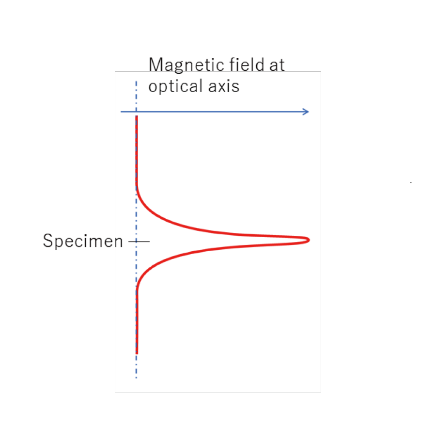
Fig. 1 Schematic of the distribution of magnetic field along the optical axis of the C-O lens.

Fig. 2 Schematic of the positions of the pre-magnetic field of the C-O lens and the specimen and the post-magnetic field. Vertical yellow lines schematically show ray paths in the STEM mode.
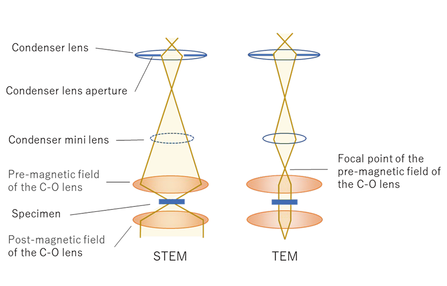
Fig. 3 Left: Ray path of the STEM mode using the C-O lens. Right: Ray path of the TEM mode, where the parallel beam is produced on the specimen using the condenser-mini lens.
Related Term(s)
Term(s) with "condenser-objective lens (C-O lens)" in the description

Are you a medical professional or personnel engaged in medical care?
No
Please be reminded that these pages are not intended to provide the general public with information about the products.


