Köhler Illumination
Köhler Illumination
A method of illuminating a parallel electron beam onto a specimen by a strong excitation of the condenser mini lens to focus the incident electron beam onto the front focal plane of the prefield of the objective lens. The illumination is used for the observation of bright-field images, dark-field images and HREM (high-resolution electron microscope) images. If the parallel illumination onto the specimen is not achieved, the diffraction condition becomes different depending on the specimen position (Fig.1(b)), which may mislead interpretation of the image.
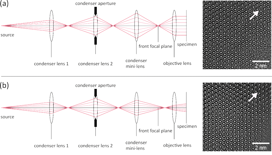
Fig. 1(a) Ray path diagram of the parallel illumination onto the specimen and a HREM image of β-Si3N4 taken at a parallel illumination condition. The incident beam is focused onto the front focal plane of the prefield of the objective lens achieving a parallel illumination onto the specimen. As a result, the images of the crystal structure are seen to be the same in all areas of the field of view.
(b) Ray path diagram of non-parallel illumination and a HREM image of β-Si3N4 taken at a non-parallel illumination condition. Since the incident beam is not focused onto the front focal plane of the prefield of the objective lens, the specimen is illuminated with a non-parallel beam. The crystal structure image looks different depending on the area in the field of view because the direction of illumination onto the specimen is different. It can be seen that the structure image indicated by the arrow is clearly different from the image indicated by the arrow in Fig. 1(a).
In recent years, in the cryo-electron microscopy field, the illumination condition without causing Fresnel fringes due to the CL (condenser lens) aperture in addition to parallel illumination shown in Fig 1(a), is called “Köehler illumination” because of its analogue to the technique of light optical microscopy. In the ordinary illumination system of TEM, the position of the CL aperture and the specimen plane are not always conjugate with respect to the prefield of the objective lens. Thus, the image of the CL aperture is not focused on the specimen position by the prefield of the objective lens, causing a non-uniform illumination onto the specimen plane accompanied with Fresnel fringes due to the CL aperture (Fig.2(a)). By adjusting the specimen position and the excitation of the objective lens so that the CL aperture and the specimen take a conjugate position, a uniform illumination without Fresnel fringes is achieved.
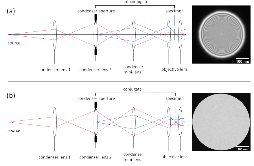
Fig. 2. (a) Ray path diagram and the image of the incident beam in the case where the parallel illumination condition is satisfied but no attention is paid to the positions of the CL aperture and the specimen. Since the position of the CL aperture and the specimen plane are not conjugate with respect to the prefield of the objective lens, the image of the CL aperture is not focused on the specimen position by the prefield of the objective lens. Then, Fresnel fringes due to the CL aperture are formed on the specimen plane (image plane).
(b) Ray path diagram and the image of the incident beam obtained by adjusting the specimen position and the excitation of the objective lens so that the CL aperture and the specimen are conjugate, in addition to the parallel illumination condition. Since the CL aperture and the specimen positions are conjugate with respect to the prefield of the objective lens, a uniform illumination without Fresnel fringes is achieved.
Related Term(s)
Term(s) with "Köhler Illumination" in the description

Are you a medical professional or personnel engaged in medical care?
No
Please be reminded that these pages are not intended to provide the general public with information about the products.


