weak-beam method
weak-beam method
The weak-beam method is a technique to take a sharp dislocation image using a weakly excited diffraction wave (reflection beam) with decreasing the dynamical diffraction effect. For example, a dark-field image of a weakly excited reflection (weak beam), e.g. of the first-order reflection, is taken at the exact Bragg setting of a high-order reflection, e.g. the third-order reflection, under a systematic reflection condition.
When a dislocation is observed using the weak-beam method, only highly strained parts of the dislocation (close to the dislocation core) appear as a black-and-white dotted line against dark background. Thus, the dislocation is more sharply imaged and the position of the dislocation is more accurately determined than when using a strongly excited reflection. As a result, the accuracy of determining whether a dislocation is extended or not is improved.
Fig. (a) shows a bright-field image taken under a two-wave excitation condition where reflection G is excited (Fig. (c)). Fig. (b) is an enlarged image of the part enclosed by a yellow square line in Fig. (a). Fig. (d) shows a dark-field image taken under the condition of Fig. (c) by shifting the objective aperture to select reflection G (Fig. (f)). Fig. (e) is an enlarged image of the part enclosed by a yellow square line in Fig. (d). Fig. (g) shows a dark-field image taken by the weak-beam method. That is, an electron beam is tilted from the condition of Fig. (c) to excite reflection 3G (Fig. (i)), and reflection G is selected with the objective aperture. Fig. (h) is an enlarged image of the part enclosed by a yellow square line in Fig. (g).
The dislocation images in Fig. (e), which were taken under a two-wave excitation condition or with a strongly excited reflection (Fig. (c)), are viewed as thick dotted lines. On the other hand, it is seen that the images taken by the weak-beam method (Fig. (h)) are sharpened.
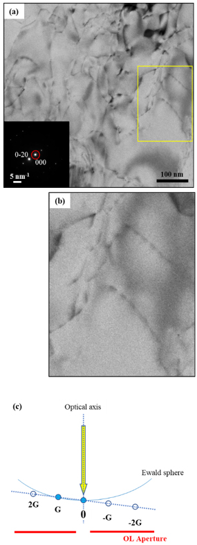
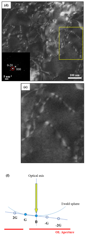
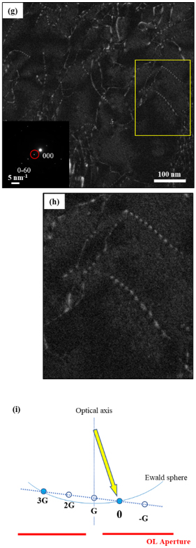
Figs. Bright- and dark-field images of dislocations in an Al alloy.
(a) a bright-field image and (d) a dark-field image taken under a two-wave excitation condition. (g) a dark-field image taken by the weak-beam method. On the lower left corner of each image (Figs. (a), (d) and (g)), an electron diffraction pattern and the position of the objective aperture (indicated by red circles) when each image was taken, are shown. Figs. (b), (e) and (h) show the enlarged images of yellow rectangular areas in the three respective images (a), (d) and (g). Figs. (c), (f) and (i) respectively show the diffraction conditions and the positions of the objective aperture (positions where the red lines are interrupted) for the bright-field image (a), the dark-field image (d) and the weak-beam dark-field image (g).
Related Term(s)
Term(s) with "weak-beam method" in the description

Are you a medical professional or personnel engaged in medical care?
No
Please be reminded that these pages are not intended to provide the general public with information about the products.


