α fringe
α fringe
"α fringe" means the edge fringes showing a specific contrast of the striped interference image obtained from a stacking fault oblique to a crystalline specimen surface, which appears in the bright- and dark-field images taken at a two-wave approximation condition. (The stacking fault is a planer defect at which an atomic displacement takes place between the two crystalline regions sandwiching the fault plane.)
Figure 1 shows the striped interference image of stacking faults intersecting oblique to the specimen surface and the illustration of the α fringe. Fig.1(a) shows a dark-field image of such two stacking faults of PbTiO3. Fig.1(b) shows an enlarged image of a part of Fig.1(a). Fig.1(c) shows a schematic of the oblique stacking fault and expected striped image, the lattice planes being displaced at the staking fault.
The atomic displacement R between the lattice planes produces the phase angle α for a diffracted wave g expressed as α=2πg・R. The end stripes or fringes, which appear at the intersection between the stacking fault and the upper and lower surfaces of the specimen, exhibit symmetric contrast in the bright-field image and anti-symmetric contrast in the dark-field image with respect to the center of the striped image (to the half depth position of the specimen). The anti-symmetric contrast (nature) in the dark field image or a dark (D)- and bright (B)-fringe pair is clearly seen in Fig.1(b).
This symmetry nature reveals the sign of the phase angle α or the sign of the displacement between the two crystalline regions, and the orientation of the fault against the specimen, that is, upward to the right (as in Fig.(c)) or upward to the left. In particular, the nature of α fringe has been used to determine whether the stacking fault of Si is the extrinsic type or the intrinsic type.
The nature and formation of the striped image depending on the phase angle α is explained by the dynamical diffraction theory taking account of the absorption effect (see Reference: Marc De Graef: Introduction to Conventional Transmission Electron Microscopy, pp499~). The term "α" fringe is originated from the phase angle α.
It should be noted that it is difficult to determine quantitatively the displacement vector between the two crystalline regions from analysis of the fringe intensity profile. For quantitative analysis, it is essential to use large-angle convergent-beam electron diffraction (LACBED). The following references are referred to detailed LACBED analysis.
- S. Yamada and M. Tanaka: J. Electron Microscopy 46 (1997) 67-74
- M. Tanaka, M. Terauchi and K. Tsuda: Convergent Beam Electron Diffraction III (1994) pp156-177, JEOL Tokyo
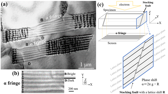
Fig.1(a) Two striped images or α fringes oblique to the specimen surface (dark-field image of stacking faults). Specimen: PbTiO3. Accelerating voltage: 200 kV. The upper fringe of the stripe is bright (B) and the lower fringe is dark (D), showing a characteristic asymmetrical contrast. It is noted that the zigzag images appearing left and right is due to zigzag overlap of two stacking faults.
Fig.1(b) Enlarged image of a part of the stripe in Fig.1(a). A pair of dark (D) and bright (B) fringes is seen. The (top and bottom) fringes show anti-symmetric contrast nature with respect to the center of the stripes.
Fig.1(c) Schematic of a stacking fault oblique to the specimen and the striped image obtained from the fault.
Related Term(s)
Term(s) with "α fringe" in the description

Are you a medical professional or personnel engaged in medical care?
No
Please be reminded that these pages are not intended to provide the general public with information about the products.


