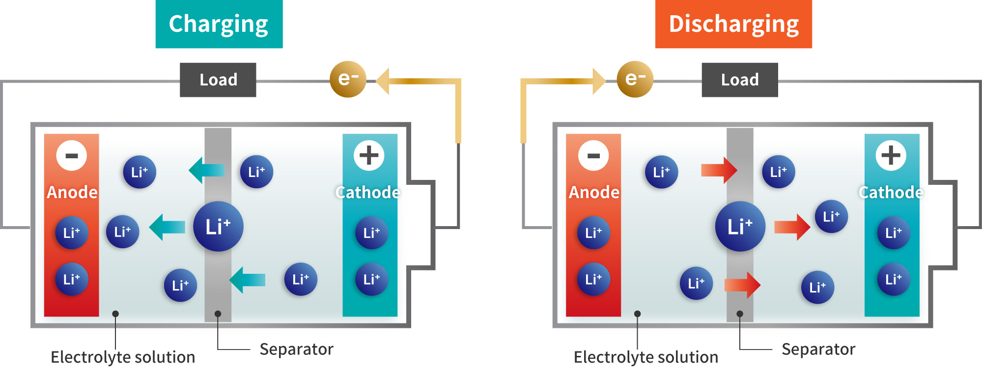
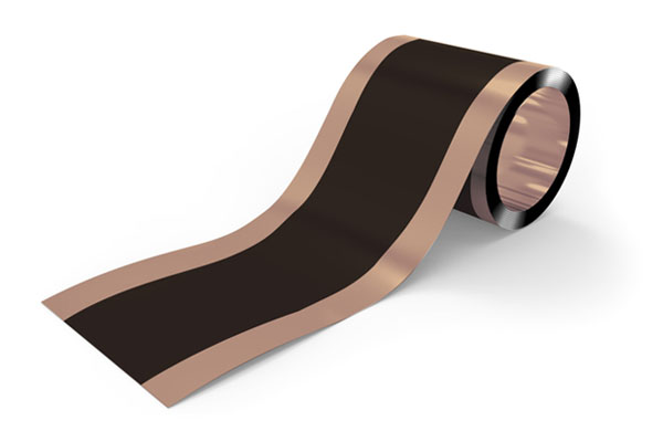
Lithium Ion Battery
The liquid-based lithium-ion batteries currently in use are referred to as
"LIBs."
LIBs charge and discharge by moving lithium ions between the cathode and anode through an
electrolyte solution.
A polymer separator is placed between the cathode and anode to prevent short circuits, and an
organic solvent-based electrolyte is used to facilitate ion conduction.
Composition and Shape of Lithium Ion Battery (LIB)
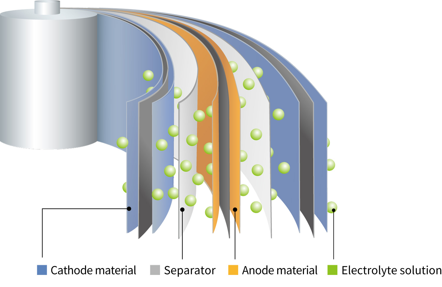
The basic structure of LIBs consists of components shown in the
figure on the right.
For the cathode, composite oxides containing lithium are used as the main active
materials. These are produced by mixing carbon materials as conductive additives with
polymer binders.
For the anode, graphite carbon capable of intercalating lithium is used and is similarly
prepared using polymer binders.
Separator films for LIBs are made of porous polymers with fine pores.
These separators serve a safety function by closing their pores in the event of thermal
runaway, thereby preventing short circuits caused by contact between the cathode and
anode.
The electrolyte solution is prepared by dissolving lithium-containing electrolytes in an
organic solvent.
For both the cathode and anode, electrode sheets are prepared by coating the respective active
materials onto a metal current collector foil.
The main battery formats are cylindrical, prismatic (rectangular), and pouch (laminated)
types.
In cylindrical and prismatic batteries, a separator is placed between the cathode and anode
sheets, which are then wound together using the winding method to form the cell.
In pouch-type batteries, in addition to the winding method, the stacking method is also used, in
which the cathode sheet, separator, and anode sheet are layered sequentially.
Cylindrical battery
Rectangular battery
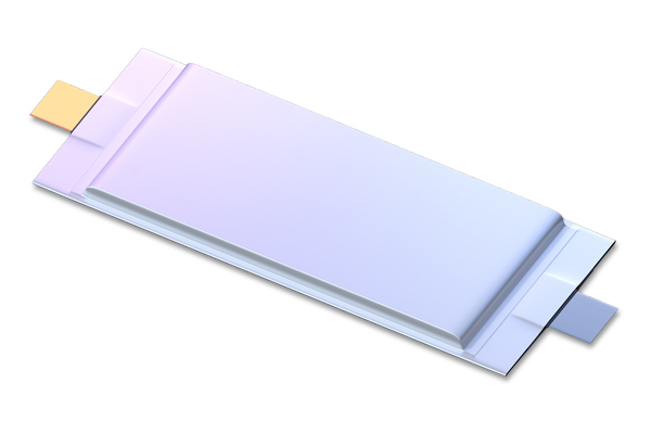
Laminated battery
Since the materials used contain highly reactive lithium, manufacturing must be conducted in an
air-isolated environment, such as a dry room.
Similarly, material analysis requires specimen preparation, observation, and analysis to be
performed under air-isolated conditions.
Therefore, air-isolated instruments and integrated systems that connect them are highly
effective for the analysis of lithium-ion batteries.
Lithium Ion Battery Note
The applications of lithium-ion batteries are expanding from mobile phones and PCs to automobiles and large energy storage systems, requiring higher performance (output, stability, etc...) and safety. Various evaluation instruments are required to improve the performance and quality of lithium-ion batteries. This LIB note introduces the features and application functions of each instrument for the material evaluation of lithium-ion batteries.
Cathode
Cathode Materials:
Active
Components in Lithium-Ion Rechargeable Batteries

Aluminum foil (left) and Aluminum foil with cathode material (right)
The cathode of a typical lithium-ion battery consists of a current
collector, cathode active material, conductive additive, and binder.
Aluminum foil is used as the current collector, and a slurry made by dissolving and
kneading the cathode active material, conductive additive, and binder in a solution is
coated onto it.
The figure on the left shows the aluminum foil current collector before the cathode
material is applied.
The figure on the right shows the aluminum foil after the cathode material has been
coated, where the black region in the center represents the applied electrode material.
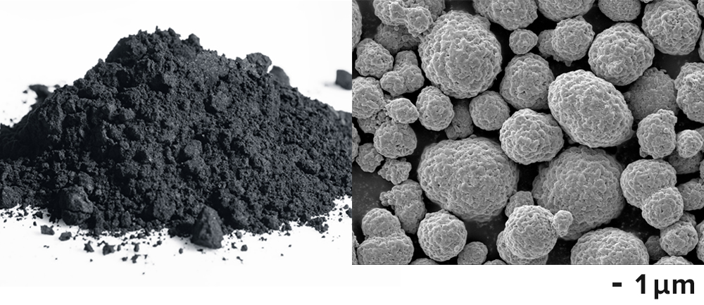
Cathode material powder (left)
Cathode material NMC811
SEM image(right)
Transition metal oxides containing lithium are used as cathode active materials.
Common materials include lithium cobalt oxide (LCO), and ternary cathode materials such
as NMC
(Li(Ni1/3Mn1/3Co1/3)O2),
where part of the cobalt is replaced with nickel and manganese. The name "NMC" comes
from the initials of the transition metals: Ni, Mn, and Co.
Another common material is NCA, composed of nickel, cobalt, and aluminum. These
materials are widely used in batteries for electric vehicles, including automobiles.
In addition, LFP (LiFePO4), which uses lithium iron phosphate as the cathode
active material, is frequently employed. Iron phosphate-based materials are known for
their high safety due to their stable crystal structure, which is resistant to collapse
even under internal heating. This minimizes the risk of thermal runaway, making them
highly suitable for automotive applications.
Moreover, since iron is less expensive than other transition metals, LFP offers
advantages in terms of production cost.
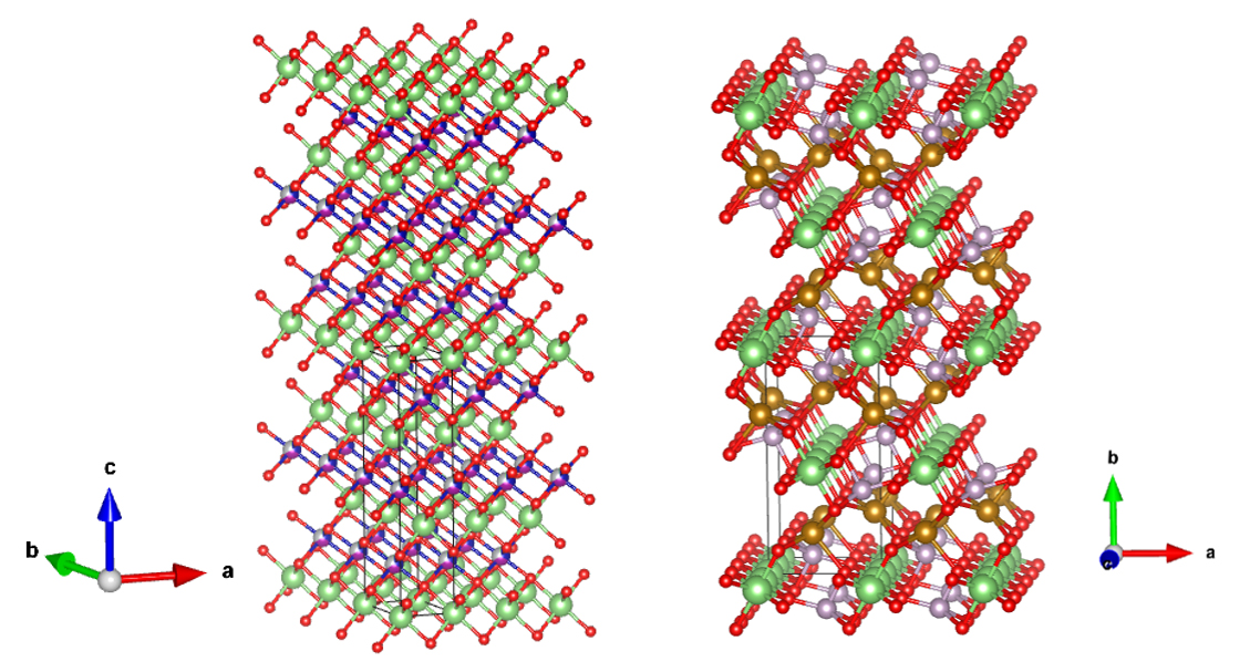
Crystal structure of cathode material
NMC/NCA Layered
Rock Salt Structure (left)
LFP Olivine Structure (right)
refer to :
J.Appl.Cryst.(2011).44,1272-1276
Each cathode active material has a theoretical capacity, which represents the amount of
electric charge corresponding to the lithium content.
However, full optimization to achieve the maximum capacity has not yet been
realized.
Development efforts are underway to create cathode materials with even higher
capacity.
In research and development, substituted versions of transition metals and materials
with modified lithium content are being actively investigated.
For evaluation during R&D, various analyses are required in addition to basic battery
performance--such as the stability of the crystal structure during lithium insertion and
extraction reactions, and the thickness and composition of surface coating layers.
| Cathode material | Average voltage [V] | Theoretical Capacity [mAh/g] | Actual Capacity [mAh/g] | Cycle characteristics | Feature |
|---|---|---|---|---|---|
| LiCoO2 | 3.7 | 274 | 148 | 500~1,000 | Expensive raw material/Relatively low thermal stability |
| NMC | 3.6 | 280 | 160 | 1,000~2,000 | Potential changes are gradual |
| NCA | 3.6 | 279 | 199 | 500~1,000 | High energy density/Relatively tolerant to low temperatures |
| LiFePO4 | 3.2 | 170 | 165 | 1,000~2,000 | Less expensive raw material/Flat potential change/Relatively high stability |
Cathode current collector foil
Aluminum foil is considered the ideal material for the cathode current collector, as it holds
the cathode active material and facilitates the transfer of electrons to enable current
flow.
It is highly conductive, corrosion-resistant, and remains unaffected by lithium-ion doping.
Its surface is naturally covered with an oxide layer, and during charging, a more
corrosion-resistant aluminum fluoride (AlF3) layer forms, allowing the cathode to
support high electric currents.
Analysis example of cathode
material
Structural
evaluation of
cathode active material
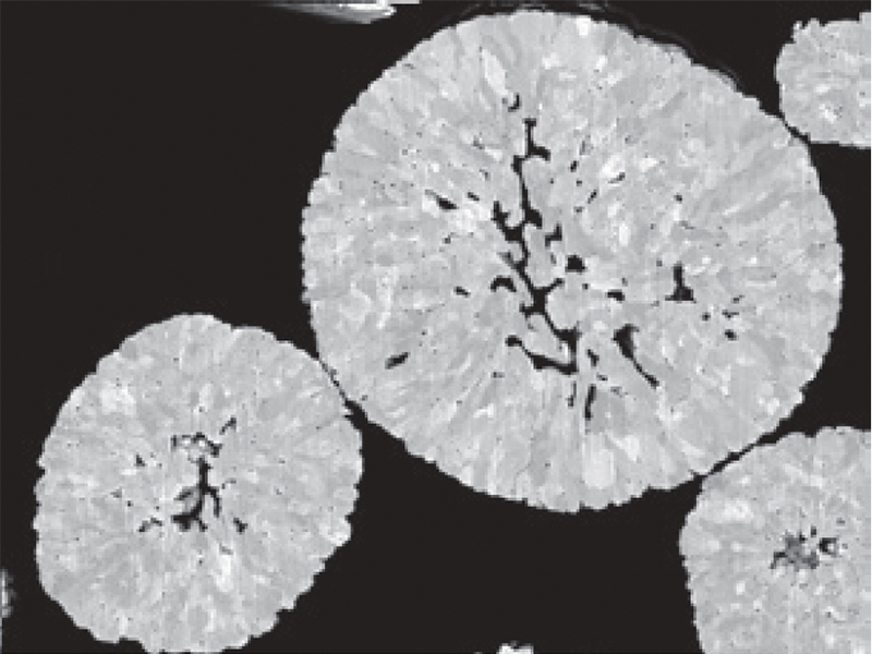
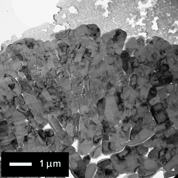
SEM Image of cathode particle cross section
Cathode active materials consist of spherical secondary
particles, which are formed by sintering smaller primary particles.
The size of the primary particles varies depending on the material, typically
ranging from several tens to several hundreds of nanometers.
During charging, lithium is extracted from the lithium-containing cathode active
material.
During discharging, lithium ions are expected to return to their original
positions within the crystal lattice.
However, due to factors such as overcharging, the lithium ions may not fully
return, resulting in structural changes.
Evaluating these structural changes is essential for understanding the
mechanisms and extent of battery performance degradation.
For structural analysis, local changes are examined using Transmission Electron
Microscopy (TEM), in addition to assessing the average structure using X-ray
Diffraction (XRD) and Raman spectroscopy.
The following examples demonstrate how crystal structure changes can be
evaluated using Raman analysis integrated with a Scanning Electron Microscope
(SEM), as well as electron diffraction and atomic-resolution imaging of specific
regions using TEM.
Another case shows the use of solid-state Nuclear Magnetic Resonance (NMR) to
analyze lithium behavior during charge and discharge cycles.
The figure below shows an example of analyzing structural changes in the cathode active
material at different states of charge using a Raman spectrometer integrated into a SEM,
as part of a combined SEM-EDS-Raman system.
The Raman spectra capture structural changes in the cathode active material at four
stages: uncharged, 50% state of charge (SOC), 100% SOC, and overcharged.
These changes are not detectable by EDS alone.
Raman spectroscopy reveals shifts in wavelength--referred to as Raman Shifts--relative to
the laser light, corresponding to changes in the longitudinal and transverse vibrational
modes between oxygen atoms in the crystal lattice as lithium is extracted during
charging.
These spectral shifts reflect alterations in the crystal structure that occur due to
variations in lithium content.
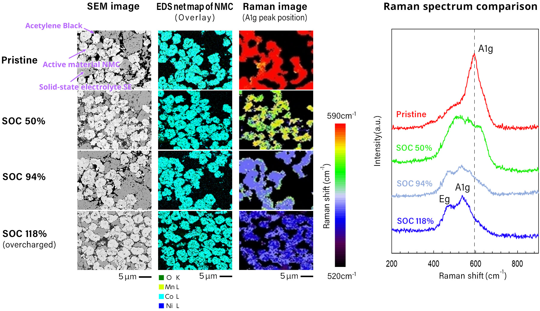
Sample courtesy:
Prof. Atsunori Matsuda
Department of Electrical and Electronic Information Engineering
Toyohashi University of Technology
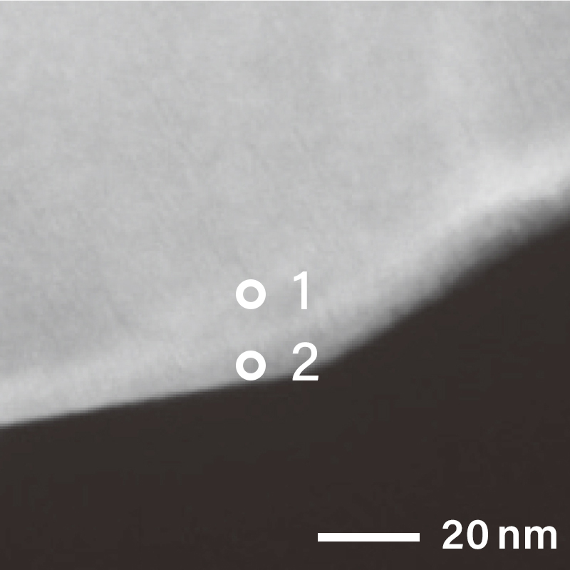
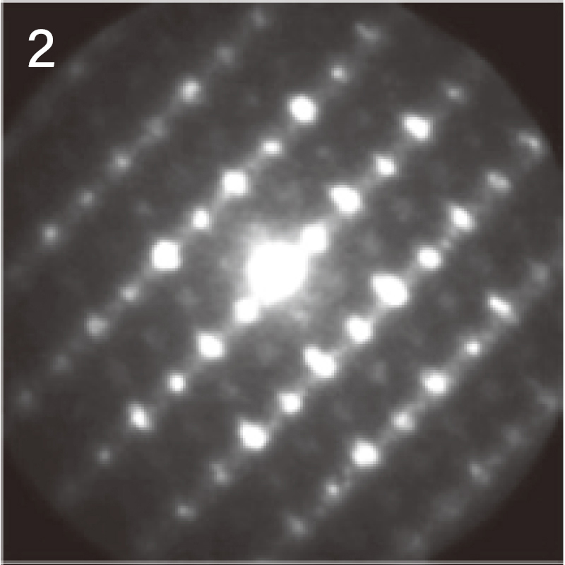
The figure below shows the electron diffraction pattern near the surface of a cathode
material particle obtained using a Transmission Electron Microscope (TEM).
Different electron diffraction patterns were observed at the surface and interior of the
cathode particle, indicating that their crystal structures are different.
For localized electron diffraction, Nano Beam Electron Diffraction (NBD) is
employed.
Using the NBD method, the diffraction pattern at analysis position "1" (inside the
particle) was identified as corresponding to the [11-20] zone axis of a layered
rock-salt structure.
In contrast, at analysis position "2" (surface), a different diffraction pattern was
observed, suggesting a structural transformation near the particle surface.
NBD patterns obtained from the surface and inside of the particle

The figure below shows the results of crystal orientation and structure analysis of
particles within a cathode active material using Precession Electron Diffraction
(PED).
PED is an electron diffraction technique that reduces dynamical diffraction effects by
precessing the incident electron beam at a fixed tilt angle relative to the optical
axis.
By collecting electron diffraction patterns at each scanned point, (a) crystal
orientation maps and (b) phase distribution maps can be generated.
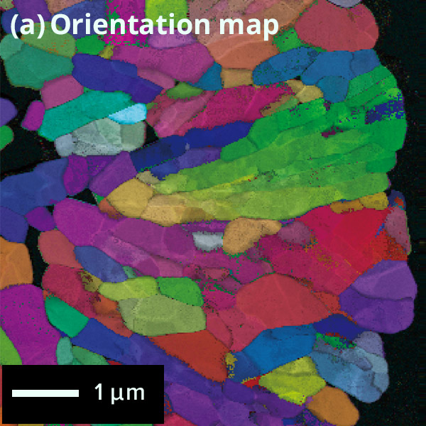
Map: Crystal orientation map of cathode active material
particle
Colored according to the crystal orientation of particles
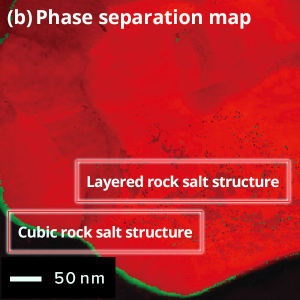
Phase Map of cathode active material
particle
Difference of
surface and inside structures in color
Red: Layered rock salt structure,
Green: Cubic
rock salt structure
The figure below shows an example of the surface of a cathode active material particle
observed before and after charging/discharging using atomic-resolution HAADF-STEM
imaging.
The triatomic layer on the electrode surface of the active material particle changes
after charging/discharging.
However, almost no atomic bright spots are visible at the sites occupied by lithium and
oxygen within the red frame. This is expected since light elements such as lithium are
difficult to detect using the STEM-HAADF method.
On the other hand, after charging and discharging, atomic bright spots appear at the
lithium sites within the red frame.
These bright spots indicate the phenomenon of cation mixing, where transition metal ions
occupy lithium sites.
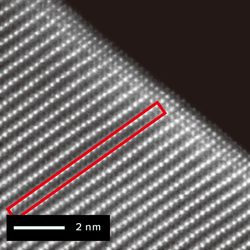
Before charging/discharging
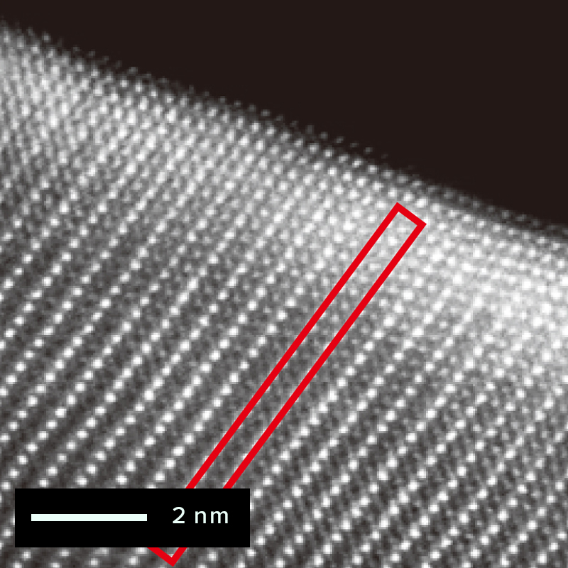
After charging/discharging
NMC structure
refer to :
J.Appl.Cryst.(2011).44,1272-1276
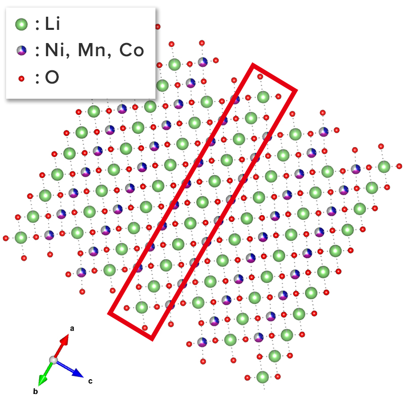
7Li solid-state NMR is an effective technique for structural analysis of
cathode active materials. Solid-state NMR can probe lithium within the crystal structure
of the entire sample and complements X-ray diffraction methods. Moreover, NMR supports
quantification of subtle structural changes observed in microscopic TEM analyses.
In the lithium spectrum of cathode active materials, a characteristic broadening over
several thousand ppm occurs due to paramagnetic interactions between transition metals
(TMs) and lithium.
Commonly used solid-state magic angle spinning (MAS) probes with diameters of 3.2 mm or
4 mm often yield spectra compromised by spinning sidebands (SSBs) caused by limited
excitation range and relatively slow sample spinning.
However, using ultra-fast MAS probes with diameters of 1 mm or less shifts the SSBs away
from the main peaks, producing clearer spectra (Fig. 1).
Furthermore, combining this with the recently developed MATPASS technique enables the
acquisition of 7Li spectra free from SSBs (Fig. 2).
Figure 2 shows an example of 7Li MATPASS spectra obtained during charging and
discharging of a lithium-rich layered cathode active material Li1.2Ni0.2Mn0.6O2.
Four major peaks are observed in the uncharged state (#1). Chemical shifts from 0 to
1000 ppm correspond to lithium in the lithium layers, while shifts from 1000 to 2000 ppm
correspond to lithium in the transition metal layers (LiTM).
Additionally, peak positions vary depending on whether the transition metal near lithium
is "Mn only" or partially substituted by Ni.
The lithium-related signals decrease during charging (#2 to #5) as lithium is extracted
from the structure, then recover upon discharge (#7) as lithium reintegrates.
Solid-state NMR thus allows the observation of lithium departure during charging and its
return during discharging via spectral changes, enabling analysis of lithium behavior
related to structural degradation.

Figure 1: 7Li Solid-state NMR spectra of MAS frequency dependence
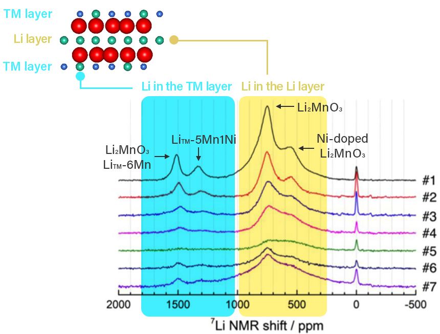
Figure 2: 7Li MATPASS spectrum reflecting
lithium in
cathode active material structure during charging and discharging
refer to : Scientific Reports (2020) 10 : 10048
Anode
Anode
Material
Anode Active Material of Lithium-Ion Rechargeable Batteries
A typical anode of a lithium-ion battery consists of a current collector, anode active material, conductive additive, and binder. Copper foil is used as the current collector. Similar to the cathode, a slurry composed of the anode active material, conductive additive, and a binder dissolved in a solvent is applied onto the current collector.
Slurry which are various materials kneaded by solution
Anode current collector with slurry applied on copper foil
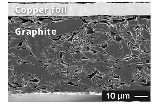
SEM image of graphite anode cross section
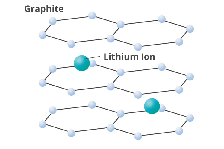
Schematic diagram of graphite with lithium ion inserted
In general, graphite is used as the active material for anodes. During charging,
lithium ions from the cathode intercalate into the layered structure of the
graphite. The theoretical capacity of graphite is 372 mAh/g. Although this is
not as high as the capacity of lithium metal (3,860 mAh/g), graphite anodes are
widely used due to their high safety and reliability.
On the other hand, silicon anodes, which offer a high theoretical capacity of
4,200 mAh/g, are being actively researched and developed. Silicon is attracting
attention as a potential alternative to carbon-based anodes because of its high
capacity and abundant availability. Despite challenges such as large volume
changes during charging and discharging, which affect cycle life, silicon is
considered a promising material for use in solid-state batteries.
Current collector foil for anode
Similar to the cathode current collector, copper foil used for the anode offers
resistance to both the electrolyte solution and oxidation, making it a
corrosion-resistant material. The operating potential of an anode with graphite as the
active material typically ranges from around 0.1 to 1.5 V vs. Li+/Li.
Although aluminum foil is lighter and less expensive, it forms a Li-Al alloy at
approximately 0.6 V vs. Li+/Li when used in anodes, which results in the
degradation of battery capacity. Therefore, copper foil--offering good resistance to the
electrolyte and oxidation, along with relatively low cost--is used for anode current
collectors.
Electrolyte Solution
Electrolyte
Solution
Electrolyte solution in lithium ion battery
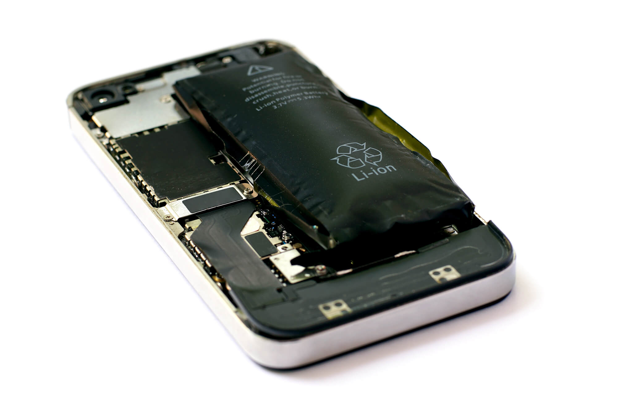
LIB expanded by the gas evolved by the decomposition of the electrolyte solution
The electrolyte solution in a lithium-ion battery plays a crucial role in
transporting lithium ions. It is an ion-conductive solution composed of an ionic
compound dissolved in a polar solvent, such as water.
In typical lithium-ion batteries, the electrolyte consists of a mixture of
organic solvents--such as ethylene carbonate (EC), dimethyl carbonate (DMC), and
diethyl carbonate (DEC)--which allow the battery to operate at high potentials
without undergoing oxidative decomposition.
However, organic solvents tend to decompose due to repeated charge/discharge
cycles, over-discharge, or overcharge, which leads to deterioration of the
electrolyte's performance.
While organic solvent-based electrolytes offer higher voltage tolerance than
aqueous electrolytes, they are flammable and are classified as hazardous
materials (flammable liquids) under fire safety regulations. In particular, if
an internal short circuit occurs due to overcharging, over-discharging, or
external shock, a large current can flow instantaneously, generating heat and
potentially igniting the flammable electrolyte.
Under overcharge conditions, cathode materials degrade, and the released oxygen
oxidizes and decomposes the electrolyte, producing gas. In over-discharge
conditions, the copper foil used in the anode may dissolve, resulting in copper
elution and the reductive decomposition of the electrolyte, which also generates
significant gas.
The electrolyte is a key material for both battery life and safety. Therefore,
research and development are underway to create electrolytes that are
non-flammable and stable at high voltages. In particular, the evaluation of
chemical stability, voltage tolerance with respect to the electrodes, and
decomposition behavior during charge/discharge cycles is becoming increasingly
important. The degradation of the electrolyte is often assessed through the
analysis of the evolved gases.
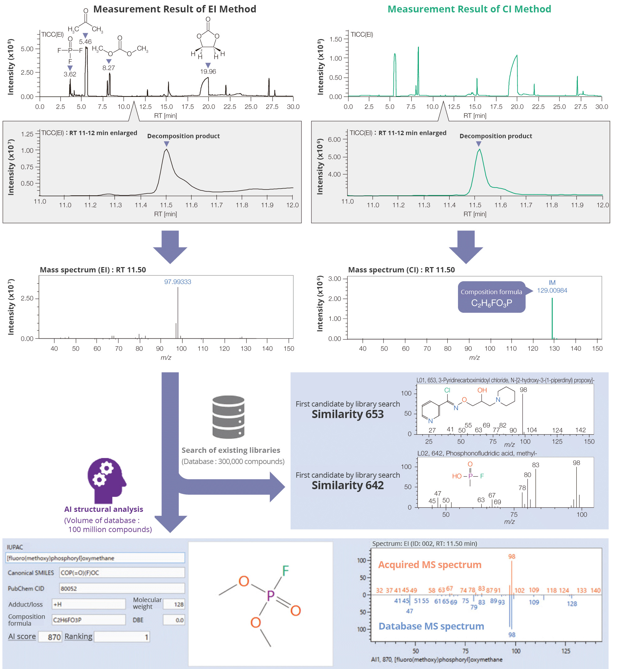
Analysis Example of
Electrolyte Solution
Degradation Analysis of Electrolyte Solution Using
AI-Assisted Structural Analysis (MS: Mass Spectrometry)
Case Study: Electrolyte Solution Degradation Analysis in LIBs
This case study analyzes the degradation of electrolyte solutions in lithium-ion
batteries (LIBs) after undergoing charge and discharge cycles. The electrolyte solution
was extracted from a disassembled battery using acetone and analyzed using a
high-performance gas chromatograph time-of-flight mass spectrometer (GC-TOF-MS).
Measurements were conducted using both the hard ionization method (EI: Electron
Ionization) and the soft ionization method (CI: Chemical Ionization). The primary
detected components included the extraction solvent (acetone), electrolyte solvents, and
the electrolyte itself. In addition, trace amounts of decomposition products from the
electrolyte and electrolyte solution were identified.
As an example, a decomposition product with a retention time of 11.5 minutes on the
Total Ion Current Chromatogram (TICC) was analyzed. Compound identification typically
requires a library search using mass spectral databases. While conventional databases
contain around 300,000 compounds, msFineAnalysis AI--our AI-based unknown
substance structure analysis software--can search a database containing approximately 100
million compounds.
Moreover, molecular weight and compositional formula information obtained from the CI
method can be used to refine search results, enabling more precise compound
identification. In this analysis, using AI-based structure analysis, the compound
C2H6FO3P (fluoro(methoxy)phosphoryl oxymethane)
was identified from over 800 candidate structures in the mass spectrum.
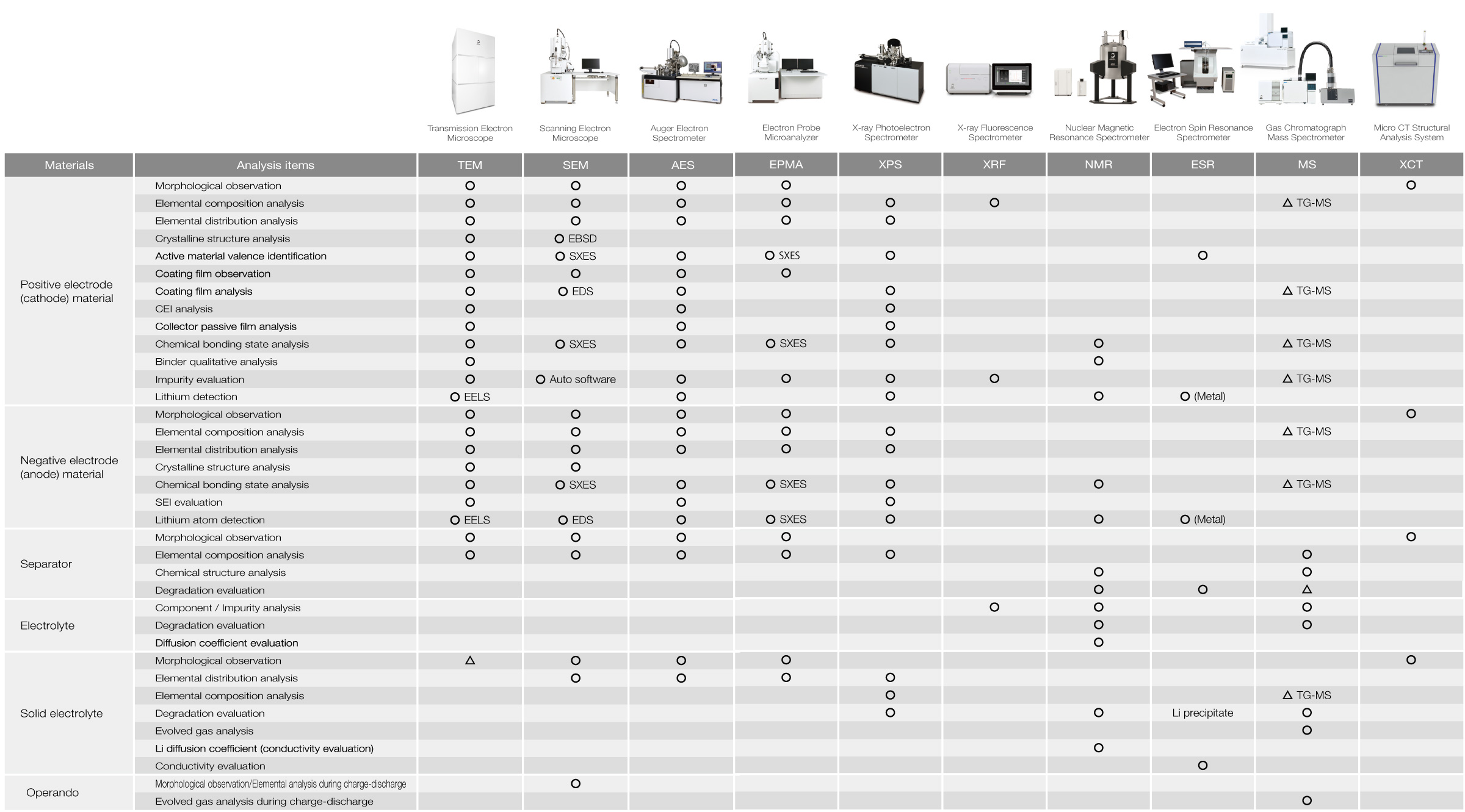
Analysis Items for Lithium-Ion Batteries (LIBs) and Corresponding JEOL Instruments
The table below lists JEOL's instruments categorized by their analytical and evaluation purposes. For more details on their applications, please refer to the catalogs and technical documents for each instrument or contact JEOL.
Importance of air-isolation transfer in battery analysis
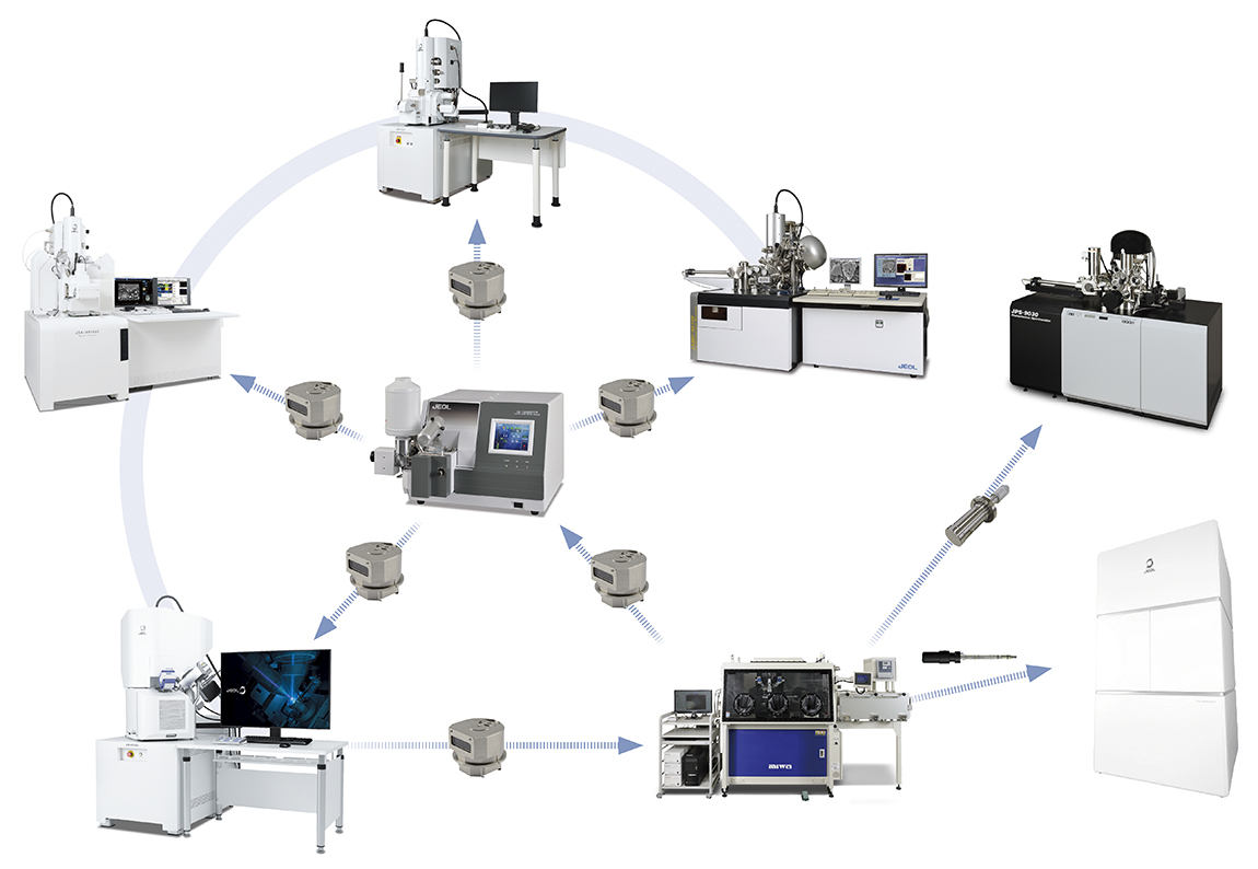
Materials used in batteries contain highly reactive lithium, which poses a risk
of alteration upon exposure to air. Therefore, manufacturing requires an
air-isolated environment, such as a dry room, and material analysis--including
specimen preparation, observation, and analysis--must also be conducted in an
air-isolated environment. Air-isolated instruments and systems that integrate
multiple analytical devices are effective for lithium-ion battery analysis.
JEOL's instrument lineup provides systems that enable processing, observation,
and analysis within an air-isolated environment.
Click the button below to return to Battery TOP
Contacts
JEOL provides a variety of support services to ensure that our customers can use our products with peace of mind.
Please feel free to contact us.