CROSS SECTION POLISHER™
Cross Section Polisher
A Cross Section Polisher (hereinafter, “CP”) is a device to prepare pristine cross sections of a specimen for a scanning electron microscope (SEM), electron probe micro analyzer (EPMA), or Auger micro probe.
Employing a new method of using a broad Ar+ ion beam and shielding plate, has made it possible to produce cross sections free of artifacts and distortion with less time and skill required than the preceding methods.
A CP can prepare cross sections of various materials such as metals, ceramics, plastics, etc., and has been utilized in various fields.
Principles of processing
The major components of the Cross section polisher (CP) are the Ar ion source, shielding plate and specimen, as shown in Fig. 1-1.
The Ar ion source ionizes Ar gas, generates Ar+ ions and, with a voltage applied, emits Ar+ ions that are accelerated to certain energy intensity. The emitted Ar+ ions (ions can be accelerated up to a maximum of 8kV) penetrate the specimen, give energy to the atoms composing the specimen, and consequently shift the position of these atoms. This phenomenon is called knock-on, and a repeatedly occurring knock-on is called a cascade collision. The phenomenon of the atoms composing the specimen being dislodged in this series of processes is called sputtering. A specimen is milled as a result of this sputtering phenomenon.
The shielding plate is made of a material which doesn’t become sputtered easily. It is placed directly above a specimen. The edge of the shielding plate is positioned at the point where the cross section observation is desired, and the specimen is irradiated with Ar+ ions. The part which is not covered by the shielding plate gets sputtered and the cross section at the edge of the shielding plate is exposed (Fig. 1-2). If hard substances and soft substances are mixed in a specimen, there will be a difference in a processing rate of the Ar+ ion beam, and as a result, a streaked roughness, which is parallel to the incident direction of the Ar+ ions, will be generated. In order to reduce this roughness, there is a mechanism designed to swing the specimen and the shielding plate (JEOL patent: No. 4557130).
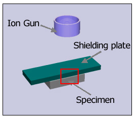
Fig. 1-1 Schematic diagram of the CP
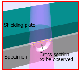
Fig. 1-2 Schematic diagram during processing
View a video of the Operation Principle of CP Processing
Please use the latest browser.
Application example , Features of processing
Using a broad ion beam, the cross section polisher (CP) can produce a surface with little roughness over a wide area (larger than 500μm).
Below are images of electronic parts taken by EPMA. From the backscattered electron image (Fig. 2-1) and elemental mapping image (Fig. 2-2), it is evident that a good quality surface with little roughness is obtained in an area as wide as 1mm2
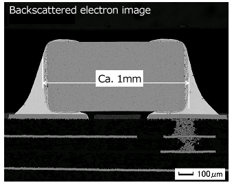
Fig. 2-1 (Electronic parts by: mobile phone sample) cross-sectional view of an electronic component according to CP
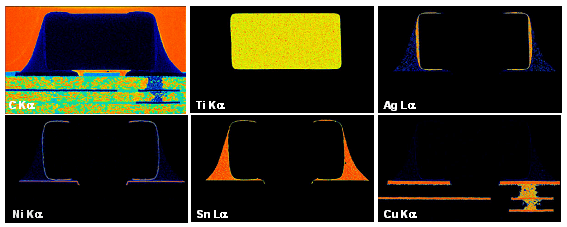
Fig. 2-2 Results of elemental mapping image
Application example , Processing method using a specimen rotation holder
The cross section polisher (CP), more effective machining can be performed by using a rotating sample holder.
The effectiveness of processing with a Cross Section Polisher (CP) can be enhanced by using a specimen rotation holder. Fig. 3-1 shows the principle of this method. In the normal process method (the method using the shielding plate), there are cases where streaked roughness becomes outstanding when cutting porous specimens or complex materials made of several substances which have different etching rates. By using the specimen rotation holder, which allows the irradiation of the Ar+ ion beam to the specimen over a 360° degree range, a cross section free of striation can be obtained even for such specimens.
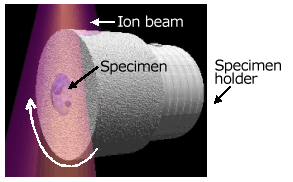
Fig. 3-1 Rotation Holder
Fig. 3-2 shows the difference between the cross section (left) produced using the standard shielding plate and the cross section (right) of the same specimen (automatic pencil lead) when using the specimen rotation holder. When comparing two, it is apparent that the latter result is better and free of striation.
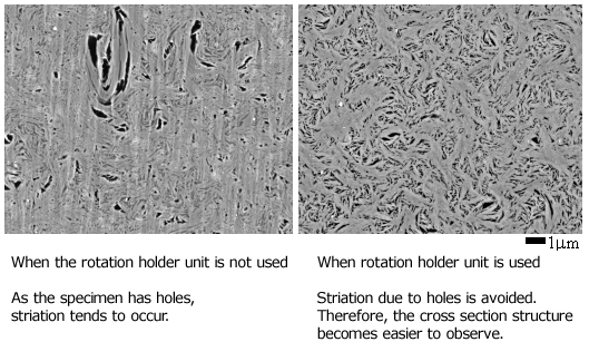
Fig. 3-2 Automatic Pencil Lead