stigmator
stigmator
A stigmator is a device which corrects an ellipse-shaped electron beam caused by the astigmatism of an electron lens to a circular electron beam.
Fig. 1 explains the force exerted on an electron beam due to the magnetic field created by an electric current through a set of coils. Two coils are placed as shown in Fig. 1(a). Coil 1a is connected to coil 2a with a copper wire, where the winding direction of each coil is opposite. When an electric current flows through the coils, the magnetic field B as shown in Fig. 1(b) is generated. Then, when an electron beam runs through the magnetic field B from the top to the bottom of the paper as shown in the figure, a force F acts on the electron beam.
Next, as shown in Fig. 2(a), coil 3a and coil 4a are added, and each coil is placed at intervals of 90°. These coils (coil 1a, 2a, 3a and 4a) are connected with a copper wire. The winding direction of the odd-number coils is opposite to that of the even-number coils. When an electric current flows through the four coils, the direction of the rotation of the magnetic field created by a coil and the coil on its left side is opposite to the direction of the rotation of that created by the coil and the coil on its right side. Consider an ellipse-shaped electron beam extending in the X direction (Fig. 2(b)), which is caused by the astigmatism of a lens, runs at the center of these coils from the top to the bottom of the paper (Fig.2(a)). Then a force that shrinks the electron beam in the X direction and extends it in the Y direction act. As a result, the electron beam is corrected to a circular shape (Fig. 2 (c)).
In the description of Fig. 2, it is assumed that the major axis of the astigmatism is in the middle of the center of the two coils. However, in the real case, the direction of the axis is arbitrary. To correct such an astigmatism, another four coils (coil 1b, 2b, 3b and 4b) are added as shown in Fig. 3. Then, the astigmatism in any direction can be corrected by adjusting the electric current Ia flowing through coils of 1a, 2a, 3a and 4a and the electric current Ib flowing through coils of 1b, 2b, 3b and 4b [1]. It is noted that the stigmator is placed at the electron source side of the objective lens.
Fig. 4(a), (b) and (c) show SEM images suffered by astigmatism. The images taken at an overfocus position (a) and an underfocus position (c) show blur in the directions orthogonal to each other. At the exact focus position (b), blur is isotropic but does not disappear. Fig. 4(e) is an SEM image taken at the exact focus position after the astigmatism is corrected, exhibiting no image blur. After the astigmatism correction, image blur is isotropic even at de-focus positions, as shown in (d) overfocus and (f) underfocus.
Reference:
[1] K. Kanaya and H. Kawakatsu, Deflection System with Eight-pole Stigmator Used in Correcting Astigmatism, Journal of Electron Microscopy, 10 (1961) 218-221.
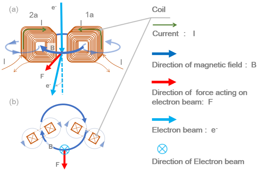
Fig. 1 Schematic illustration of the deflection of the electron beam due to the magnetic field created by a set of two coils.
(a) Two coils are placed as is shown in the figure, where the winding direction of each coil is opposite. When an electric current flows through the two coils, the magnetic field B is generated. (b) When an electron beam e- runs through the magnetic field B from the top to the bottom of the paper, a force F acts on the electron beam to deflect the beam.
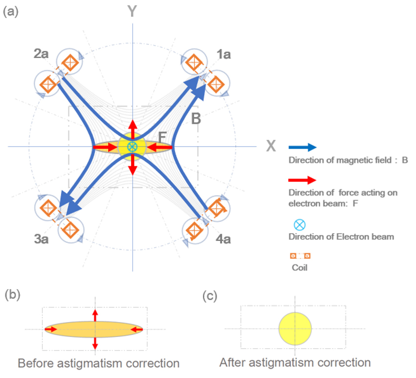
Fig. 2 Schematic of a stigmator which consists of four coils.
A magnetic field shown in (a) created by a set of the four coils corrects an ellipse-shaped electron beam extending in the X direction (b) to a circular electron beam (c).
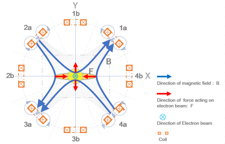
Fig. 3 Schematic of a stigmator which consists of eight coils.
Four coils 1b, 2b, 3b and 4b that are the same as those shown in Fig. 2 are added and placed at intervals of 45°. The winding direction of the odd-number coils is opposite to that of the even-number coils. The amount of the electric current flowing through coils 1a, 2a, 3a and 4a and the amount of the current flowing through coils 1b, 2b, 3b and 4b, are the same. By adjusting the electric current, the astigmatism of a lens is corrected.
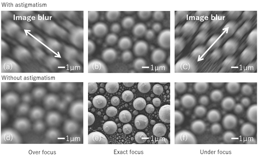
Fig. 4 Change in SEM images at different focal positions with astigmatism and without astigmatism.
When the astigmatism exists, the images taken at an overfocus position (a) and an underfocus position (c) show blur in the directions orthogonal to each other (indicated by arrows). At the exact focus position (b), image blur is isotropic but does not disappear. Thus, the specimen edges are not clear in the image.
When the astigmatism is corrected, image blur is isotropic at an overfocus position (d) and an underfocus position (f). At the exact focus position (e), image blur disappears. Thus, the details of the specimen surface are clearly seen.
Specimen: Ball of tin/Carbon pellet. Accelerating voltage: 5 kV. Working distance: 4 mm. Probe current: 176 pA.
Related Term(s)
Term(s) with "stigmator" in the description
Are you a medical professional or personnel engaged in medical care?
No
Please be reminded that these pages are not intended to provide the general public with information about the products.


