High-resolution STEM Image Acquisition Method for Tilted Specimen Using a New Type of Aberration Corrector
EM2025-05
Introduction
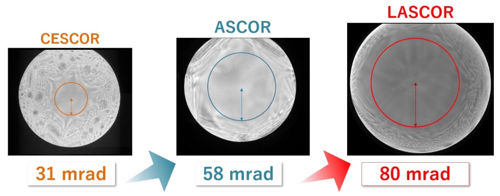
CEOS's new three-hexapole type aberration corrector LASCOR enables the correction of hexapole three-lobe aberration, which was not possible with the conventional ASCOR. This technology innovation has extended the Ronchigram flat area of NEOARM equipping LASCOR, to convergence semi-angle 80 mad or so. In this study, we suggest a new method to acquire a high resolution STEM image by utilizing the extended flat area and precisely aligning the zone axis with electromagnetic operation. The utmost feature of this method is that it does not depend on the stage operation. Therefore, it can avoid mechanical problems such as backlash and drift, and can efficiently automate the acquisition of high-resolution STEM image. This technology is expected to be applied to the semiconductor field above all. As a concrete measure, first of all, make the beam vertically enter toward the zone axis which is off the optical axis, by using the deflection system inside LASCOR which is placed right beneath the CL aperture. Then, return the beam to the center of the detector by using the deflection system located in the lowest of the imaging lens system and acquire STEM image. Due to the wide flat area, there is almost no influence from geometrical aberration although the beam is tilt by 60 mrad or so. However, chromatic aberration and beam tilt affected the image quality. The image was confirmed to be blurred toward the tilting direction of the beam.
Background
In order to acquire a high-resolution STEM image, it is necessary to precisely align the zone axis of the sample. For zone axis alignment, the mechanical dual axes tilting mechanism is used by holder and goniometer, however, the backlash and drift that occurs during zone axis alignment can matter. These mechanical issues make it difficult to automate STEM image acquisition and it is required to establish a zone axis alignment method which does not rely on mechanical operation. On the other hand, the STEM aberration correction technology is greatly advanced. CEOS developed LASCOR which is three-hexapole type STEM aberration corrector. The LASCOR is capable of correction of hexapole three-lobe aberration, a high order aberration, which is difficult with the present ASCOR. Therefore, the NEOARM with LASCOR has extended the Ronchigram flat area as large as 80 mrad. This presentation reports an electromagnetic zone axis alignment method by utilizing the extended flat area.
Electromagnetic zone axis alignment method
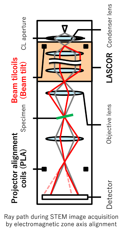
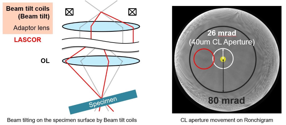
For electromagnetic zone axis alignment, two deflection systems are used: Beam tilt coils located in the upper LASCOR and PLA located at the lowest of imaging lens system. With the Beam tilt coils, the dual deflection can tilt beams genuinely, thus the beam is tilted on the specimen surface.
The PLA swings back the beam that is off the detector center by tilting the Beam tilt coils, to the center. When the beam is tilted, the CL aperture shadow shifts on the Ronchigram. If this shift is within the flat area, a STEM image can be acquired without introduction of geometric aberration. When a CL aperture of convergence semi-angle 26mrad(φ40μm) is used, high-resolution STEM image can be obtained by tilting the beam to 54mrad(3.1°)on the Ronchigram that has been extended to 80 mrad.
Result
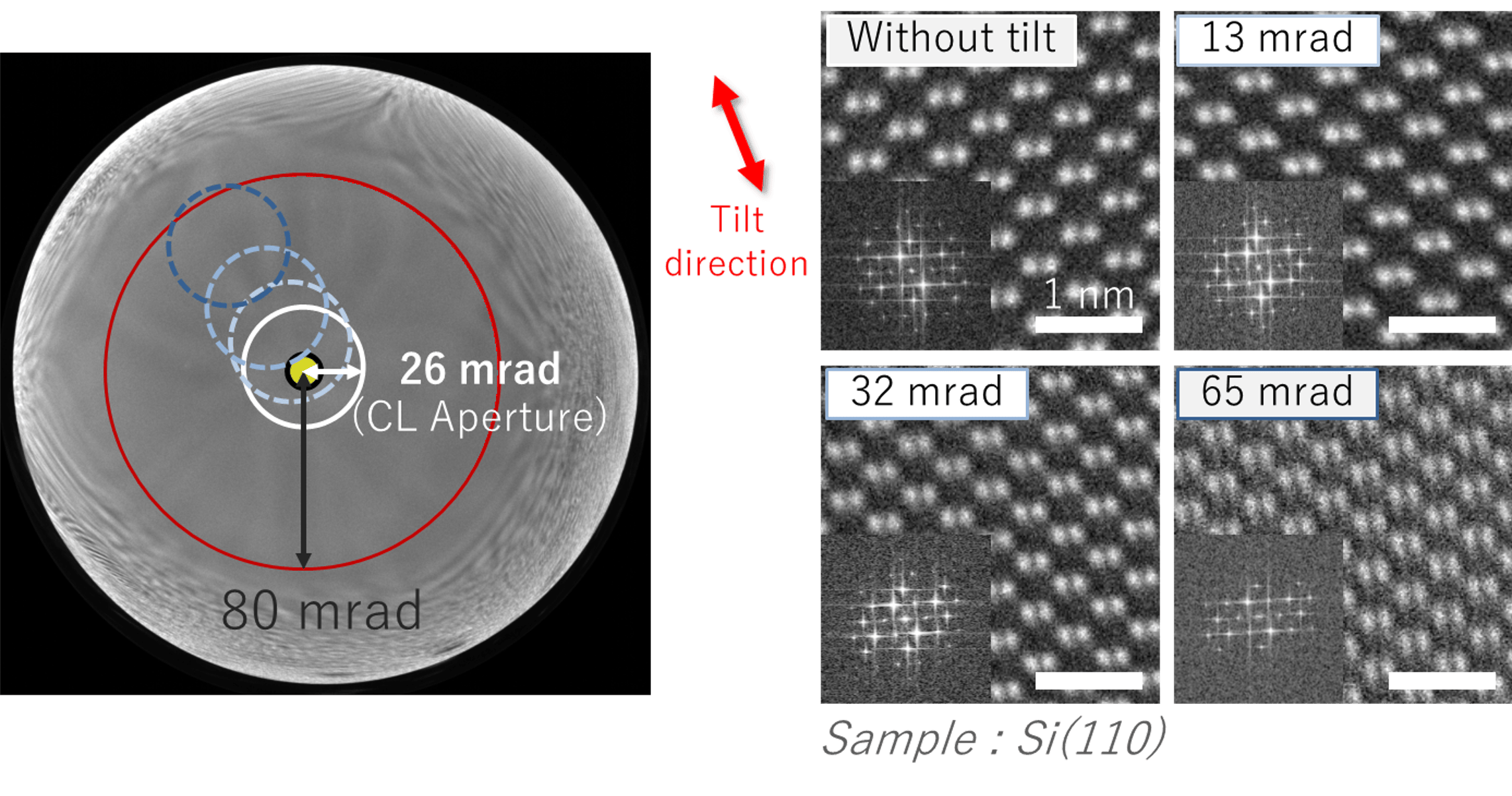
The experiment was performed by using the NEOARM(JEM-ARM200F) with LASCOR. The left figure shows the Ronchigram obtained during the experiment. The dotted lines indicate the position of the CL aperture when the electromagnetic alignment of zone axis was performed. In this experiment, the tilting of Si(119) was adjusted, to enable the correction of zone axis for 4 different angles(0.13.32.54 mrad) and STEM images were obtained for each angle. The right figure shows the observation results. Even when the zone axis is 65 mrad shifted, image was obtained with Si(110) atomic resolution. However, the image blurred more toward the tilt direction, depending on the degree of tilting.
Consideration
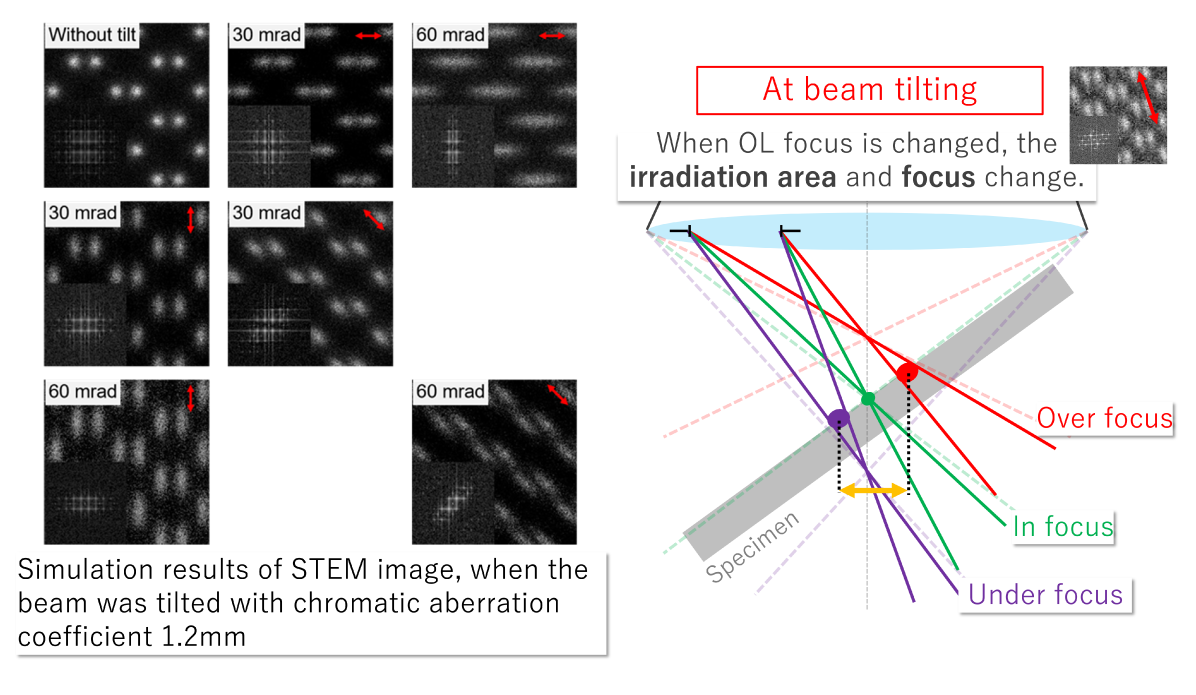
We considered that the blurring of the STEM image towards tilting direction was caused by the chromatic aberration and the beam tilting. Chromatic aberration is caused by variations in electron energy and it appears as a slight focus change. In this zone axis adjustment method, the beam is tilted on the specimen surface. So, it is like this in the right figure for the tilting direction. As you can see from this figure, when the focus is changed, the irradiation position to a specimen and the focus change. This change is considered to appear as a blur in the tilted direction. In the left figure, only the chromatic aberration was introduced by 1.2mm and the simulation result when the beam tilting state was reenacted. In this simulation image, we could confirm the blur similar to what was observed in the experiment. These results shows that for the STEM image acquisition by electromagnetic zone axis alignment, chromatic aberration and beam tilting can affect the image quality.
Conclusion
We considered a STEM image acquisition method through zone axis alignment only by electromagnetic operation. Acquisition of atomic resolution image was possible even when the STEM image was acquired with the beam tilted by 65mrad. On the other hand, blurring of the STEM image was confirmed when the beam is tilted, due to beam size and beam tilting direction. Simulation results using the multislice method confirms that the blur was due to the influence of chromatic aberration and the beam tilting. Thus, we came to the conclusion that the electromagnetic zone axis alignment technology can be a stronger tool when chromatic aberration becomes smaller due to monochromater and others.
Reference
H Müller et al., Microscopy and Microanalysis, 12 (2006) p. 442.
S Uhlemann et al., Microscopy and Microanalysis, 28 (2022) p. 2630.
Solutions by field
Electrical / Electronic Component
Related products
Are you a medical professional or personnel engaged in medical care?
No
Please be reminded that these pages are not intended to provide the general public with information about the products.