Mass spectrometry imaging on mixed conductive/non-conductive substrate using JMS-S3000 SpiralTOF™
MSTips No.288
Surface analysis methods such as EPMA, AES, or XPS can provide chemical information about element type, bonding states, or functional groups. However, few methods can obtain the molecular-structure information of organic compounds. Matrix-assisted laser desorption/ionization time-of-flight mass spectrometry (MALDI–TOFMS) is a soft ionization technique that can determine elemental composition by accurate mass analysis and can obtain structural information using MS/MS. Recently, MALDI mass spectrometry imaging (MSI), which can map the spatial distribution of organic compounds, has become popular. In MALDI–TOFMS, high voltage is applied to a target plate, accelerating ions into the TOFMS usually set at ground potential. Therefore, conductivity is required for the target plate, and stainless steel is often used for solvent-based analysis. In MALDI–MSI, a tissue section about 10 μm thick is placed on an indium tin oxide (ITO) glass slide to provide conductivity on the sample surface.
In the industrial field, there is interest in measuring organic compounds on non-conductive substrates, such as resins a few millimeters thick. If the mass spectrum is obtained from the non-conductive surface with no pre-treatment, the mass resolution will be lower, and ultimately the ion intensity will decrease significantly due to the charge-up effect. This issue can be solved by providing conductivity to the non-conductive part via the gold deposition method.[1] In this report, MSI is performed using a permanent red marker on a substrate with a conductive part and a non-conductive part. Previously, ions could be observed only from the conductive part. Now, with the gold deposition method, they can be observed from both the conductive and the non-conductive parts, and they can be properly mapped.
Experiment
To create a model substrate, we formed conductive and non-conductive parts using metal patterns (Au 100 nm/Cr 30 nm) on a 1-mm-thick quartz glass substrate, alternating conductive with non-conductive parts at intervals of 400 μm (Figure 1). We used a red permanent marker to ionize the main component without applying a matrix compound. The letters "MS" were written with this marker so that they straddled the conductive and non-conductive parts on the model substrate. We then fixed the model substrate and the stainless-steel target plate with conductive tape (Figure 2). MSI measurement was performed without gold deposition. Thereafter, we used gold deposition on the same sample and performed MSI measurement again. All MSI measurement were performed in SpiralTOF™ positive-ion mode. Pixel size was 50 μm; number of laser shots was 50 per pixel.
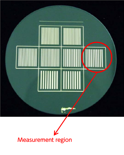
Figure 1. Scheme of the model substrate.
The conductive and non-conductive parts were laid out in an alternating pattern on quartz glass.
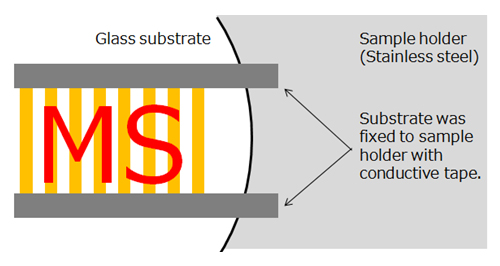
Figure 2. The model substrate was fixed with conductive tape on a target plate.
Results
Figure 3 shows the results of MSI measurement without gold deposition. At upper left is an optical image with the black parts corresponding to a conductive part. At upper right is a mass image of Rhodamine B (C28H31N2O3+), which is the main component of the permanent red marker. At bottom is an image of overlapped optical and mass images. It is difficult to read the letters "MS" on the mass image because the ions were observed only from the conductive part. The region of interest (ROI) mass spectra, which were created in two regions for each of the conductive parts (ROI1, -3) and non-conductive parts (ROI1, -4), are shown in Figure 4. These are monoisotopic peaks of Rhodamine B ions. The ions cannot be observed from the non-conductive regions, ROI2 and ROI4. Even in the conductive regions ROI1 and ROI3, mass resolution was lower than could have been obtained using the gold deposition method described below. Such results pose a problem because if the ion can be detected only from the conductive part, the target compounds will not appear in the non-conductive part, whether they actually exist or not.
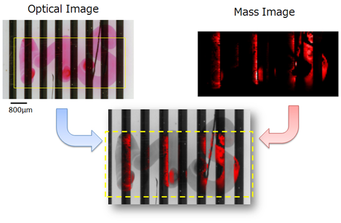
Figure 3. The result of MSI measurement without gold deposition.
The region of interest (ROI) mass spectra, which were created in two regions for each of the conductive parts (ROI1, -3) and non-conductive parts (ROI1, -4), are shown in Figure 4. These are monoisotopic peaks of Rhodamine B ions. The ions cannot be observed from the non-conductive regions, ROI2 and ROI4. Even in the conductive regions ROI1 and ROI3, mass resolution was lower than could have been obtained using the gold deposition method described below. Such results pose a problem because if the ion can be detected only from the conductive part, the target compounds will not appear in the non-conductive part, whether they actually exist or not.
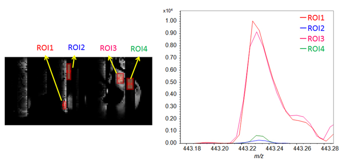
Figure 4. The ROI mass spectra from the conductive parts(ROI1 and 3) and non-conductive parts (ROI2 and 4) on model substrate without gold deposition
The results of MSI measurement after gold deposition are shown in Figure 5. At upper left is the same optical image as in Figure 3. At upper right is a mass image of the ion (C28H31N2O3+) derived from the main component Rhodamine B. At bottom is an image of overlaid optical and mass images. The ions were detected from both the conductive and non-conductive parts, which the letters "MS" can be read . Figure 6 shows the ROI mass spectrum at two places in each of the conductive and non-conductive parts. The observed peak is the monoisotopic ion of Rhodamine B (C28H31N2O3+). In contrast to the results without gold deposition, ions can be observed from ROIs 2 and 4 of the non-conductive part, as well as from ROIs 1 and 3 of the conductive part. In addition, high resolution can be realized in all areas, and the influence of charge-up is considered sufficiently small.
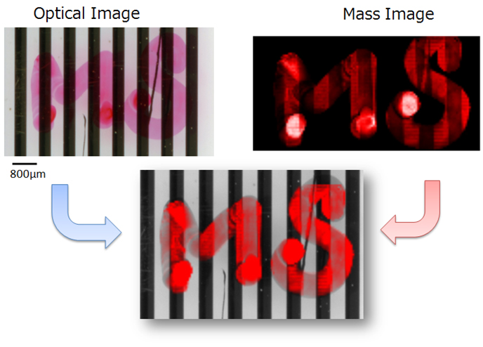
Figure 5. The result of MSI measurement with gold deposition.
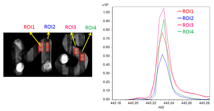
Figure 6. The ROI mass spectra from the conductive parts(ROI1 and 3) and non-conductive parts (ROI2 and 4) on model substrate with gold deposition.
Conclusion
If MSI measurements are taken of an organic compound that is placed directly on a conductive/non-conductive mixed substrate, the charge-up effect will influence the results. The ion intensity of the non-conductive part will be too low, and nothing will appear in the non-conductive parts on mass images. The gold deposition method is an easy way to solve this issue by adding conductivity to the sample surface.
Reference
[1] MSTips No. 251, “Analysis of organic compounds on an acrylic plate using JMS-S3000 SpiralTOF™.”
- If you want to see a printed version, please click this PDF file.

PDF 896KB
Related Products
Are you a medical professional or personnel engaged in medical care?
No
Please be reminded that these pages are not intended to provide the general public with information about the products.
